10. Air-Based Power Cycles¶
Air-Based Power Cycles
Build Your Own Combustion Cycle: the Essential Starter Pack
Introduction¶
In this final chapter, we cover the cycles of engines that use air as a working fluid. These are sometimes called gas power cycles, although because the term gas engine is understood differently in different contexts,
we choose the term air-based engine in this book. Chapter 10 aims to answer the same two questions as its predecessor with liquids/vapors:
• Why and how are air-based engines used today?
• Why are we moving away from ideal cycles and how do we quantify these compromises?
10.1 Why Use an Air-Based Engine?¶
The use of air as a working fluid, rather than water, brings several advantages.
• First, it is possible to completely dispense with condensers and coolers. The cooling phase (§7.2.1) takes place directly in the atmosphere, which easily accommodates all the hot gases that are rejected, and which serves as a reservoir from which to draw fresh air to feed into the engine.
For an equal power level, the mass, volume, and often the cost of air-based engines are therefore greatly reduced compared to their steam counterparts. This is particularly interesting when the engine must contribute to carrying its own weight.
• Second, the heat input is carried out without loss. It is now possible to have the combustion occur directly within the working fluid – this is why we speak of internal combustion engines – and thus to avoid the heat loss associated with a boiler (§9.3.3).
The main drawback of air-based engines is that internal combustion requires a high-quality fuel. Since the combustion residues must flow inside the thermodynamic part of the machine, we cannot use economical or otherwise advantageous heat sources such as the combustion of waste, wood, or coal.
Ultimately, the relatively lower weight of air engines compared to their steam counterparts means that they are systematically used when mass plays an important role, such as in air or road transport.
10.2 Evaluation of Air-Based Engines¶
10.2.1 Thermal efficiency¶
It now goes without saying that we always seek to achieve a high thermal efficiency, approaching its theoretical maximum (7/6).
As we have already suggested in §9.2, thermal efficiency should not, however, be maximized at the expense of other important parameters, the most notable of which we present below for air-based engines.
10.2.2 Work ratio¶
In a running engine, the irreversibility of compressions and expansions is not independent of speed. When they operate outside their optimal operating range, engines thus see their specific power decrease. Irreversibilities can even reduce efficiency to zero, with the engine running without producing useful work (as would a disengaged car engine). The work ratio is a concept that assesses the robustness of a cycle to the increase of these irreversibilities.
In order to address this concept, let us first study the case of an engine whose arbitrarily-chosen energy flows are described in figure 10.1; in this engine, compressions and expansions are reversible. Now, if instead of being ideal, the turbine suddenly saw its isentropic efficiency drop down to , it would supply . The net power of the engine would then decrease from 10 to – a reduction of .
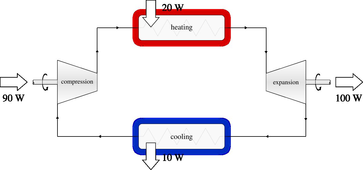
Figure 10.1:The cycle of a hypothetical engine with low work ratio. The delivered power is , and the efficiency
Diagram CC-0 Olivier Cleynen
Let us now compare this case with an engine of the same efficiency, same power, but with a different cycle, as shown in figure 10.2. In that new engine, if the isentropic efficiency of the turbine went from to , the net power would decrease from 10 to – a decrease of only .
We can see here that the larger the share of the turbine power in the net power delivered, the less the cycle efficiency is affected by irreversibilities. We generalize and formalize this “turbine share” with the concept of work ratio , defined as the ratio between the net power and the gross power of an engine:
where is the work ratio (dimensionless); is the shaft power released during expansions;
and is the shaft power received during compressions.
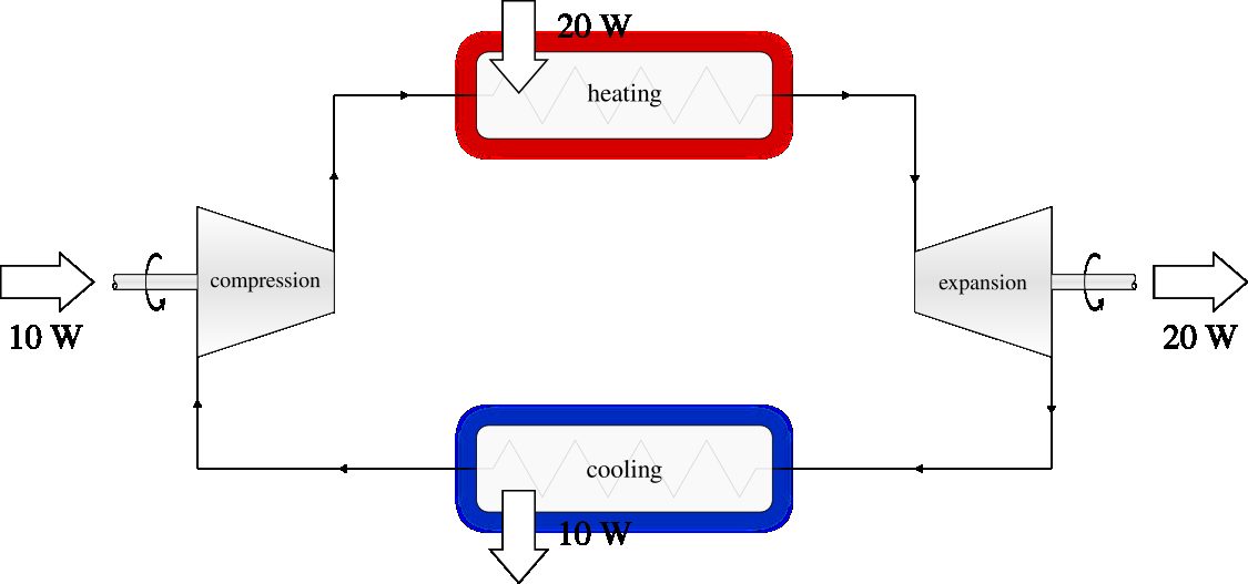
Figure 10.2:The cycle of a second (also hypothetical) engine, with a high work ratio. The delivered power, and the efficiency
are identical to those of the engine described in figure 10.1. Diagram CC-0 Olivier Cleynen
A machine with a large work ratio loses less of its efficiency when operating outside its optimal speed range: it is therefore more flexible in use. The work ratio is one of the indicators of an engine’s responsiveness, namely, its ability to change power and speed quickly. A parallel can be drawn with the concept of net profit margin in economics: all else being equal, it is more interesting to sell items bought at 2AC for 3AC than items bought at 100AC for 101AC, notably because the profit of 1AC is then less sensitive to a change in price or cost imposed by the market.
The Carnot engine is the typical example of a thermodynamic cycle with high efficiency but low work ratio. By plotting the cycle on a pressure-volume diagram (figure 7.10 p. 188), this weakness is evident: the curves during the compression and expansion phases are very close to each other. Rankine, when he modified this cycle (§9.4.2), significantly increased the work ratio.
In general, obtaining high thermal efficiency requires a high compression ratio (so as to achieve a high temperature before heat transfer is initiated). Obtaining a high work ratio requires low compression work (so as to minimize the engine’s sensitivity to irreversibilities). These two objectives are often contradictory, and it will be up to the engineer to find the best compromise.
10.2.3 Specific thrust and specific power¶
We use the concepts of specific thrust and specific power , in other words, the thrust and power of the engine divided by the mass flow rate of air passing through it, to compare engine cycles succinctly. Increasing these parameters is often desirable in applications where a high power-to-weight ratio is sought.
For example, a heavier aircraft must provide greater lift, which increases drag, and in turn the thrust, and finally the power required to generate it – so in that case, an increase in efficiency is not always justified if it results in an increase in weight or size.
10.2.4 Other evaluation criteria¶
Many more criteria need to be considered in the design of an engine, which we will not explore in this book. They include:
• purchase cost, which is directly related to the complexity and size of the engine;
• ecological impact;
• ease of maintenance and reliability;
• responsiveness;
• the level of vibration generated.
Taking into account each of these factors can justify deliberately limiting the efficiency of the engine. Indeed, when the student acquires their first motor vehicle, they will likely attach more importance to the purchase cost than to the energy consumption – and in the same way, they may not choose to fit it with a racing engine requiring constant maintenance.
Truth be told, there is very little to add to what our eminent and favorite theorist already explained in 1824:
One must not flatter oneself for ever exploiting, in practice, the entirety of the motive power contained in combustibles. Attempts that one would make to approach this result would prove more harmful than beneficial, if they led to the neglect of other important considerations. The economy of fuel is but one of the conditions to be fulfilled by fire machines; in many circumstances, it is but secondary, and must often yield precedence to the safety, the solidity, the durability of the machine, to the small amount of space that it must be made to occupy, the low cost of its establishment, etc. Knowing how to appreciate, in each case, at their true value, the considerations of convenience and economy that may present themselves; knowing how to discern the most important from those that are merely accessory, weighing them all properly against one another, so as to attain by the easiest means the best possible result, such must be the principal talent of the man [or woman] called upon to lead, to coordinate between them the labors of his [or her] fellow beings, to make them converge toward a useful end, of whatever nature it may be.
Sadi Carnot, 1824 [4]
10.3 Reciprocating Engines¶
Reciprocating engines, often called piston engines, take in a finite amount of air and perform their thermodynamic cycle on this mass. The cycle is repeated several times over time, and often several times in parallel, in order to provide continuous power. An automobile engine typically performs about fifty cycles per second.
10.3.1 Advantages of piston engines¶
From a thermodynamic perspective, the main advantage of these engines is that it is much easier to manipulate a fixed mass of air than a continuous flow. Manufacturing a cylindrical piston to fit tightly in a cylindrical bore is comparatively simple, and this allows the volume and pressure of the fluid to be precisely controlled. For example, it is possible to carry out combustion at a constant temperature (as prescribed by Carnot) by varying the volume during combustion. The same operation in a steady flow machine would require combustion to take place in a turbine (§4.4.4 p. 98), which is much more challenging.
Another advantage of piston engines is that the maximum temperature of the cycle is only reached sporadically (periodically, but always briefly). During combustion, it is thus possible to reach gas temperatures that exceed the metallurgical limits of the engine, which, as we saw in chapter 7 (the second law), improves efficiency.
On the other hand, the weight and complexity of mechanisms of piston engines (connecting rods, crankshaft, valves, and the various circuitry to and from the cylinders) become major disadvantages in applications where very high powers and rotational speeds are required.
10.3.2 The Otto cycle¶
The German engineer Nicolaus Otto is credited with the development of the engine known today as the petrol or gasoline engine in 1864. The basic cycle of this engine, called the Otto cycle, consists of two isentropic phases framed by two isochoric phases; it is described in figure 10.3.
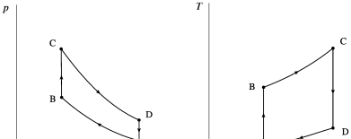
Figure 10.3:Otto’s theoretical cycle represented on pressure-volume and temperature-entropy diagrams. These diagrams depict the ideal path, without irreversibilities in the compression or expansion.
Diagrams CC-0 Olivier Cleynen
The Otto cycle is designed to allow for a simple implementation of the heat addition phase. The fuel is mixed with air before being inserted into the engine, and a very rapid combustion is triggered with a spark when the volume in the cylinder is minimal: this is known as spark ignition. Otto originally intended his engine for stationary applications, but its relative simplicity and responsiveness would ensure its success in transportation (notably through his son Gustav Otto, an aircraft manufacturer whose company would later become bmw).
The efficiency of the theoretical Otto cycle is easily calculable. The heat input is performed at constant volume (equation 4/22). The heat rejection, in practice, is done outside the engine, after exiting the exhaust pipe. From a thermodynamic point of view, the air continues its cycle in the atmosphere before re-entering the engine (§6.2.1), and thus the heat rejected is . Thus, since in theory no heat transfer takes place in the compression and expansion phases, and if we consider that the properties of the gas do not change during combustion, the efficiency of the theoretical cycle is simply given by:
By defining the compression ratio as:
it is possible to show that Equation 10/2 can be reformulated to express the efficiency as:
This equation indicates that the efficiency of the Otto engine depends solely on the compression ratio, and not on the amount of heat supplied during combustion. This may at first be surprising: why does , the maximum temperature of the cycle, no longer appear here? The answer is that in this cycle, as the amount of burned fuel is increased, the increase in the average temperature during heat addition is exactly offset by the increase in the average temperature during heat rejection.
Equation 10/4 owes its simplicity to the fact that we neglected the change in air properties during combustion, as well as the irreversibilities during compression and expansion. It should therefore be used with great caution; however, the trend it describes remains valid. Engineers are constantly seeking to increase the compression ratio of their engines to enhance efficiency. An immediate limit to this ratio is the temperature at which the air-fuel mixture spontaneously ignites, causing premature combustion.
10.3.3 The Diesel cycle¶
The Diesel engine, the child of his patient and hard-working inventor, German engineer Rudolf Diesel (§7.6), powers today the overwhelming majority of commercial road and marine transportation.
From a strictly thermodynamic point of view, the theoretical Diesel cycle differs from the Otto cycle only in its combustion mode: heat addition occurs at constant pressure and not at constant volume, as shown in figure 10.4.
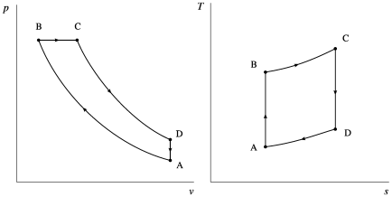
Figure 10.4:Theoretical Diesel cycle represented on pressure-volume and temperature-entropy diagrams. These diagrams depict the ideal path, without compression or expansion irreversibilities.
Diagrams CC-0 Olivier Cleynen
Since the heat addition (equation 4/17) is done simultaneously with the production of work, there is no simple expression for the efficiency , which no longer depends solely on the compression ratio. It will need to be calculated by studying the cycle step by step. It will then be observed that all else being equal (same compression ratio and same maximum temperature), the Diesel cycle has a lower efficiency than the Otto cycle.
In order to understand the interest of this cycle and the true difference between a Diesel engine and a gasoline engine, some historical context is needed. In 1892, Rudolf Diesel designed a “rational” engine to implement the Carnot cycle. He was looking for two characteristics:
• a high compression ratio, to increase the air temperature before combustion;
• combustion at a constant temperature.
To achieve this, Diesel had to wait until the end of compression to inject the fuel, in order to avoid premature ignition. The isothermal heat addition requires a progressive combustion. Thus, the original Diesel engine is inherently equipped with direct fuel injection, independent of air intake. The Diesel cycle is interesting because it enables a higher compression ratio and combustion quality compared to the Otto cycle.
Diesel’s engine evolved continuously from the impractical concept described in the 1893 Theory and Construction of a Rational Heat Engine Intended to Replace the Steam Engines and Combustion Engines Known to Date [23, 24] and isothermal combustion of coal powder) to the first production models he developed at the manufacturer MAN and isobaric combustion of petroleum). Like Otto, Diesel initially focused on stationary engines (his first prototypes were single-cylinder and over three meters high), but it was ultimately applications in commercial transportation, where its excellent efficiency and operating economics gave him the advantage over spark-ignition engines, that brought his work fame.
10.3.4 Implementation of the cycles¶
The two cycles described above are only idealizations – they serve as conceptual standards for comparing actual cycles. Their implementation in a real engine requires taking into account numerous factors, including:
• the need to purge the air and combustion products from inside the cylinder after the cycle, and the impossibility of doing it completely;
• the fact that the volume occupied by the gas is linked to the rotation of the engine shaft, and that it therefore is not possible to control it independently of the engine’s operating speed;
• irreversibilities during compressions and expansions caused by fast piston movements;
• heat transfers to and from the cylinders during the cycle;
• gas leaks (blow-by) in the clearances between pistons and cylinders.
Once these factors, as well as the pursuit of objectives related to user comfort and control of air pollution, are taken into account, the cycle obtained inside a cylinder of a practical engine may for example resemble the one represented in figure 10.5. In the automotive sector in particular, the adoption of direct injection and the increase in compression ratios for gasoline engines to reduce fuel consumption and emissions has blurred the gasoline/Diesel distinction – gasoline engines are now closer to Rudolf Diesel’s concept than to Nikolaus Otto’s.
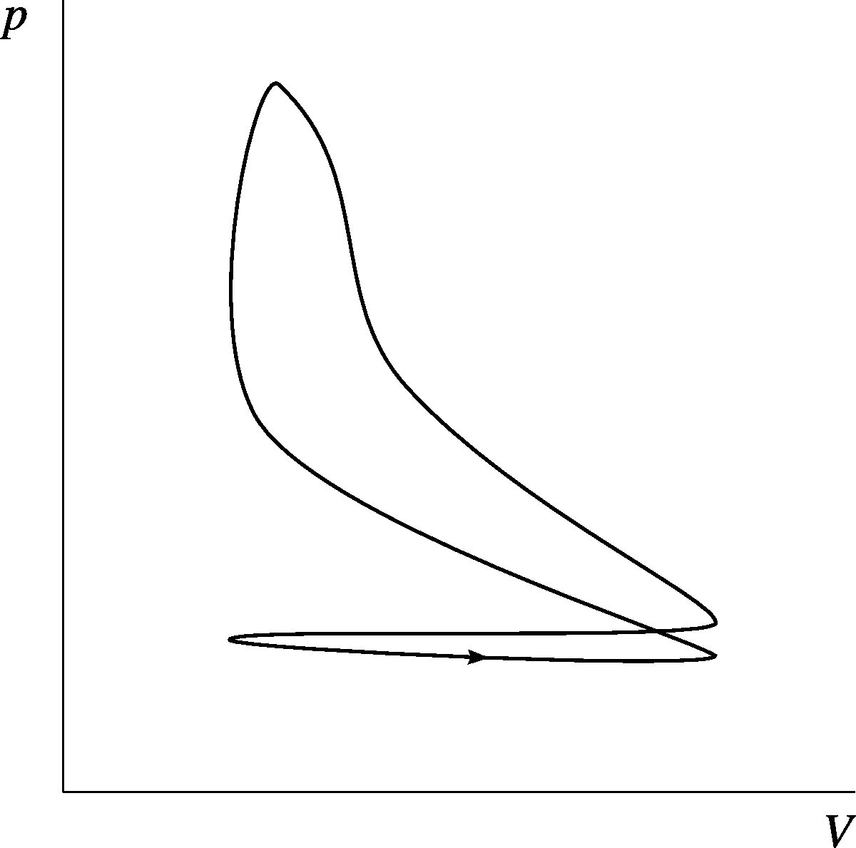
Figure 10.5:A realistic representation of the pressure and volume changes during a cycle in a practical gasoline engine.
Diagram CC-0 Olivier Cleynen
10.3.5 Number of cylinders and turbocharging¶
An important drawback of reciprocating engines is that the irreversibility of compressions and expansions increases significantly with the piston speed in the cylinders. The traditional approach to overcome this issue is to increase the number of cylinders operating simultaneously in the engine (figure 10.6). This way, the stroke traveled by each piston for a given displacement volume can be reduced. An advantage associated with this approach is that the motion of mechanical parts is better balanced (and the engine sounds more harmonious!).
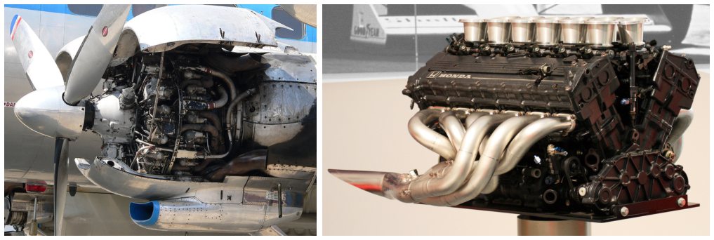
Figure 10.6:On the left, a 1950 Curtiss-Wright r-3350 Duplex-Cyclone of with 18 cylinders arranged in two successive rows. Four of these engines powered the long-range aircraft Lockheed Super Constellation. On the right, a 1991 Honda ra121e V12 engine. It powered the McLaren mp4/6 Formula 1 car.
Photo of the Duplex-Cyclone CC-by-sa by Frank C. Müller Photo of the V12 ra121e CC-by-sa by Commons User:Morio
Unfortunately, the mechanical complexity, size, and manufacturing and maintenance costs of engines increase rapidly with the number of cylinders; therefore, in applications where these factors are crucial (such as the majority of the automotive sector, for example), usually only four, or even three or two cylinders are used. It is nevertheless expected that these engines operate efficiently over a wide range of power outputs.
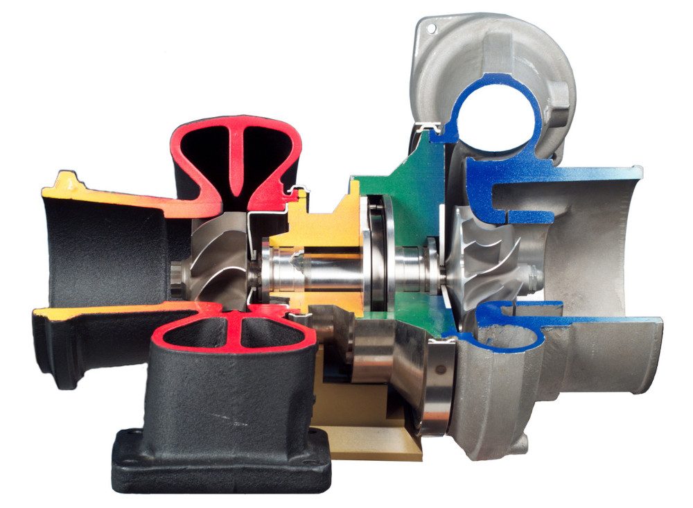
A commonly adopted solution for this is turbocharging. It involves delegating some of the compression and expansion work to a small device called a turbocharger or simply turbo, which is compact and lightweight (figure 10.7). The turbo’s compressor is powered by its turbine, which operates with exhaust gases (we will study this system further in §10.5.2). Turbocharging helps increase the specific power (that is to say, it reduces the size and speed of an engine for a given power output).
Since the use of a turbocharger negatively affects the responsiveness of an engine, it is possible to allow the intake air to bypass it while the engine speed is changing. Furthermore, temperature changes in the turbo can be compensated for by cooling before insertion into the cylinders (this technique is studied further in §10.6.1). These processes make modern engines complex thermodynamic systems capable of performing a wide range of very different cycles depending on operating conditions.
Figure 10.7:A cutaway view of a turbo to show its internal arrangement. Atmospheric air enters from the right and is compressed as it is propelled outward by the centrifugal compressor; it is then fed into the engine. Exhaust gases enter from the center left and exit to the left after spinning the centripetal turbine, which powers the compressor via the central rotating shaft. Since the only moving part is very compact (about here), very high rotation speeds can be achieved, typically exceeding .
Photo nasa (public domain)
10.4 Components of Gas Turbomachinery¶
Before delving into the cycles of turbine engines, we will briefly review the operation of their main components. Since turbomachines operate with steady fluid flow, we will consistently refer to the concepts of chapter 3 (open systems) from now on.
10.4.1 Compressor¶
The compression and expansion phases in engines are often adiabatic, and always irreversible. It is difficult to achieve high-quality flow in the compressor, more so than in the turbine because the pressure gradient promotes boundary layer separation. It is a heavy, bulky component with complex geometry (Figures 10.8 and 10.9). Most compressors are axial, meaning that the air passes through them parallel to the axis of rotation, but sometimes centrifugal compressors are used, which sling the air radially; regardless of the method used, the thermodynamic process undergone by the air remains the same.
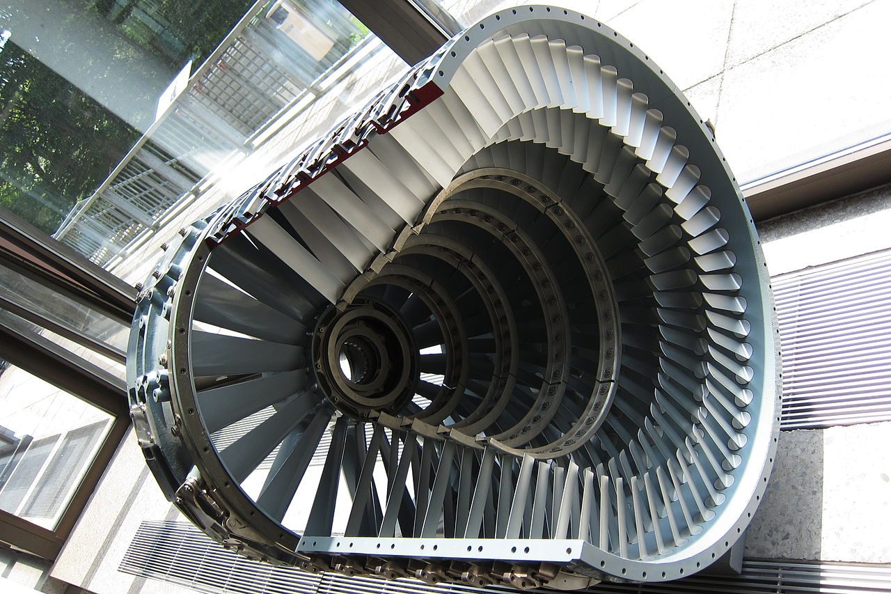
Figure 10.8:The stator casing which houses the rotor (not shown) in an axial compressor of a turbojet engine.
Photo CC-by-sa Olivier Cleynen
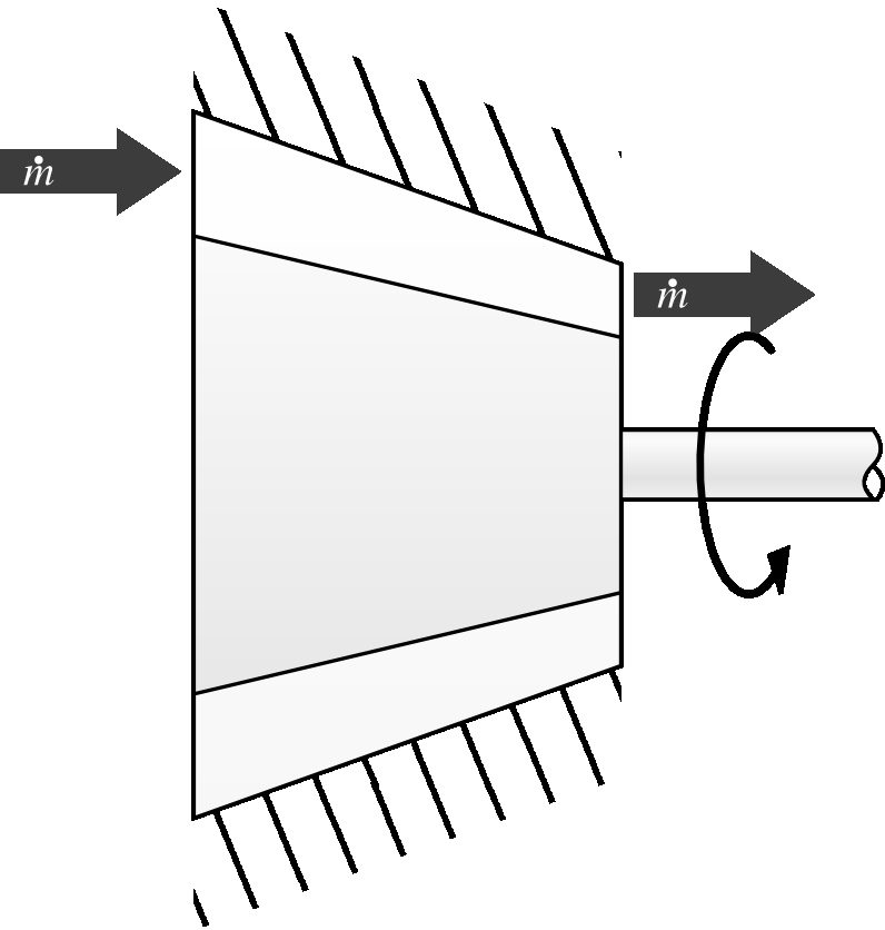
Figure 10.9:Schematic representation of an air compressor.
Diagram CC-by-sa Olivier Cleynen
Just as we did for the turbine (9/6), we quantify the efficiency of a compressor by comparing its power with that of an ideal compressor (one that would be isentropic). We call this parameter the isentropic efficiency of the compressor:
where is the actual shaft power received by the compressor, and is the power of an isentropic compressor that would operate with the same mass flow rate and between the same pressures.
Like that of a turbine, the isentropic efficiency of a compressor is always less than 1. If this efficiency is known, we can compare the actual properties of the air at the inlet and outlet of the compressor with those that would be measured in the ideal case:
where is the specific power of the compressor , is the ideal outlet temperature (isentropic compressor) ,
and is the actual outlet temperature .
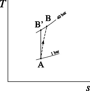
In practice, several air bleeds can be made within the compressor to feed other equipment and to cool the turbine (10.6.3). During transitional phases, the compressor can also be relieved of part of the mass flow by allowing air to leak through discharge valves.
10.4.2 Combustion chamber¶
The heat input of turbomachines takes place in one or more combustion chambers (figures 10.10 and 10.11). The air is heated at constant pressure by combustion; its temperature and specific volume greatly increase.
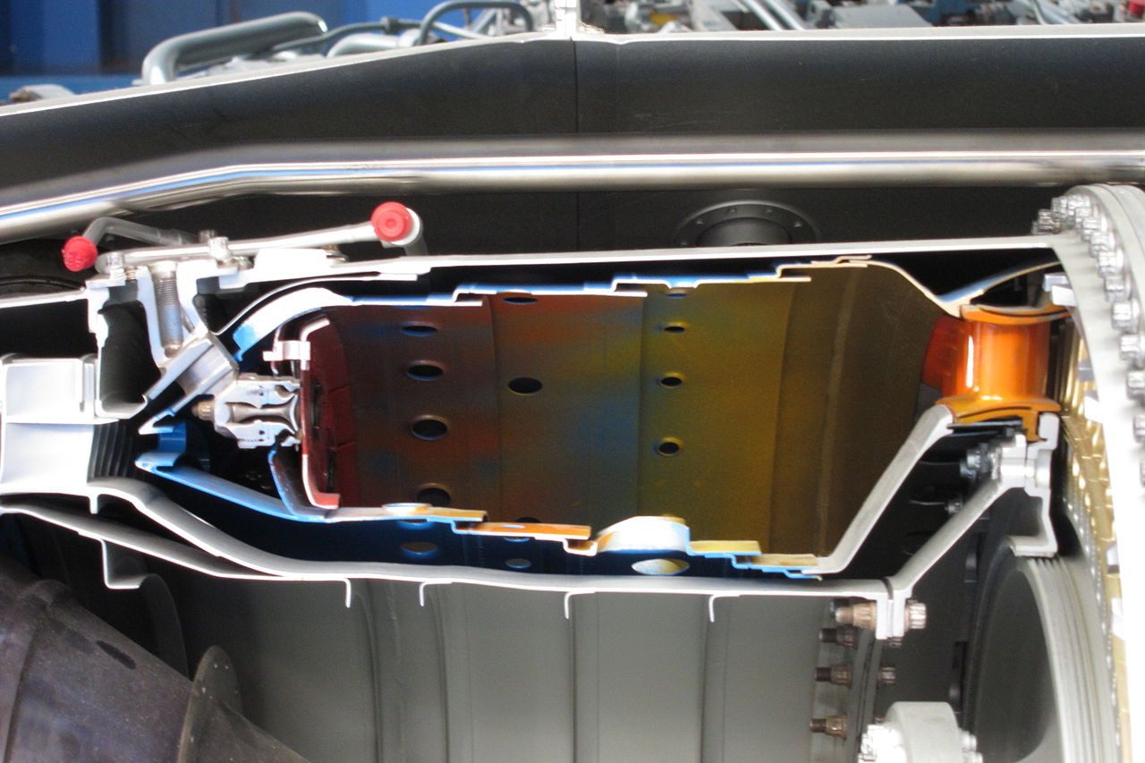
Figure 10.10:Section of an annular combustion chamber in which the flow was from left to right. The photo shows a section of a Rolls-Royce Turboméca Adour, a small turbofan engine designed in 1968.
Photo CC-by-sa Olivier Cleynen

Figure 10.11:Schematic representation of a combustion chamber.
Diagram CC-0 Olivier Cleynen
No work is done in the combustion chamber, and the pressure remains approximately constant. Since the heat input occurs within the gas itself, the maximum temperature of the cycle is not limited by heat transfer through a solid wall. The maximum temperature of the air can even exceed that of the melting point of the chamber walls, which are insulated with several layers of compressed air. Compared to steam power plants, this allows for a temperature increase of about .
The power delivered in the combustion chamber is quantified rather easily by modifying equation 4/19 to account for the change in air properties during combustion, which increases the value of by about :
Fluid flow within the combustion chamber depends in a correlated manner on combustion chemistry and the spatial distribution of velocities and pressure: it is therefore difficult to model. In practice, a slight pressure drop is generated between the inlet and outlet of the chambers. The influence on the turbine power of the fuel mass flow rate, always much lower than that of air, can be safely neglected.
10.4.3 Turbine¶
The primary role of the turbine (figures 10.12 and 10.13) is to power the compressor: it must therefore extract enough power from the air to operate the latter and compensate for any transmission losses. Depending on the configuration of the turbomachine, the turbine may then be designed to further extract energy from the gases in order to power other components, as we will see in §10.5 below.
Just like for liquids/vapors (eq. 9/6 p. 247), we measure the performance of a turbine by quantifying its isentropic efficiency :
The power extracted by the turbine is thus easily expressed in terms of the actual and ideal temperatures at its outlet:
As the gases flow downstream through the turbine, they expand and their specific volume increases. The size of the blades (hence their weight and cost) must also increase, while the power they can extract decreases. Gases are often rejected at the outlet of a turbomachine with residual pressure because it is not economically viable to extract any more work from them.
10.4.4 Nozzle¶
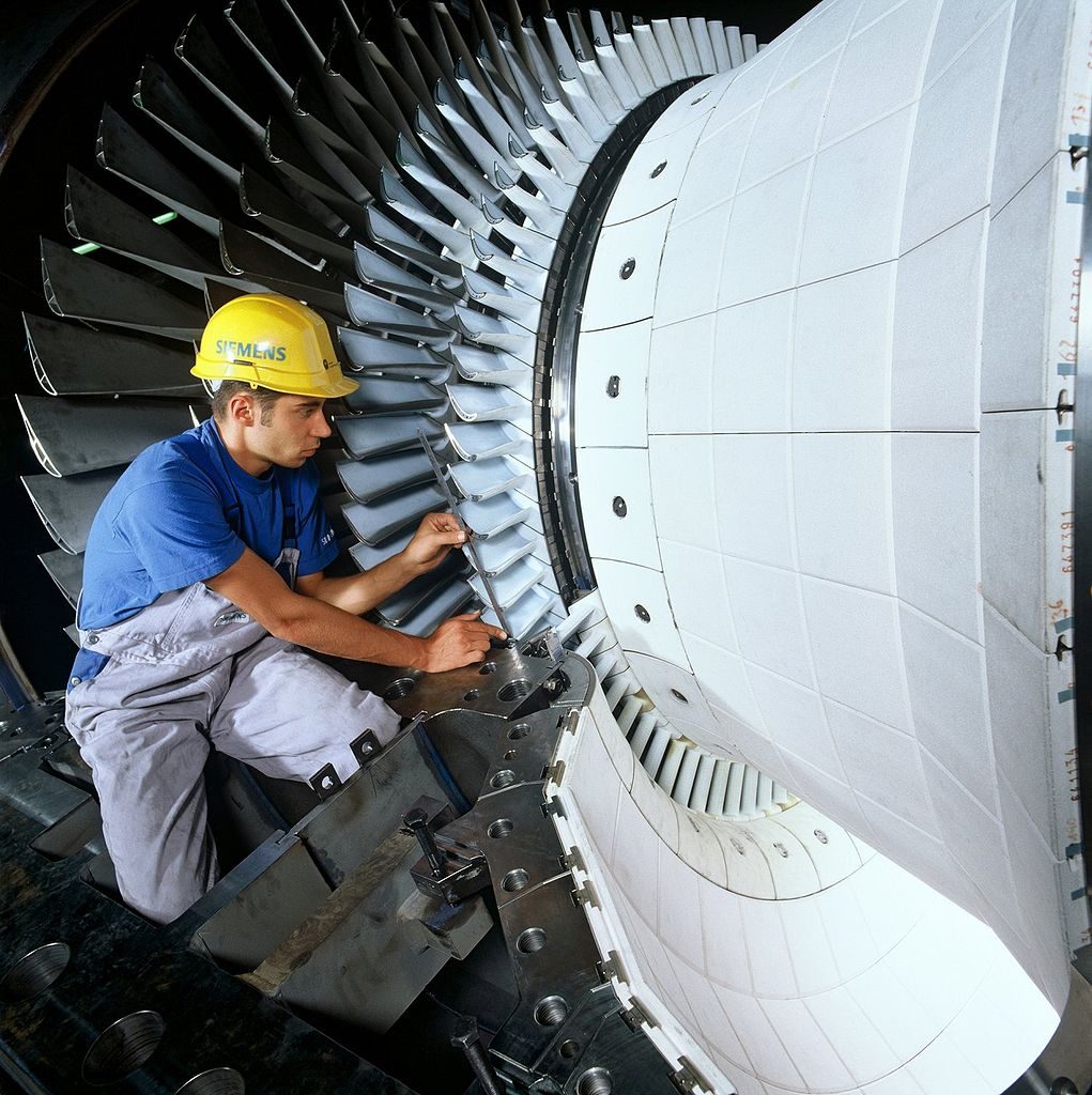
Figure 10.12:Turbine of a gas generator. The photographed turbine, a Siemens sgt5, can accept an air and water flow rate of . It delivers approximately of shaft power.
Photo CC-by-sa Siemens Pressebild
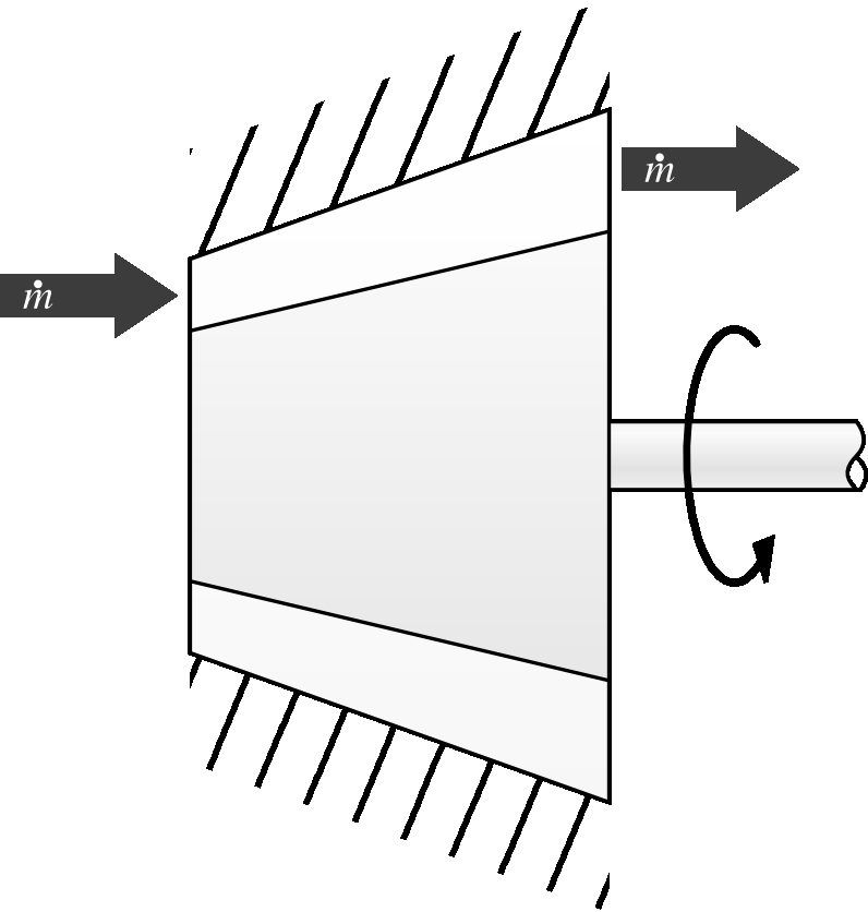
Figure 10.13:Schematic representation of a gas turbine.
Diagram CC-by-sa Olivier Cleynen
The nozzle is a simple conduit with no moving part (figures 10.14 and 10.15).
It allows the gas to expand, thereby accelerating towards the rear of the engine. It is this increase in gas velocity (difference between inlet and outlet velocities) that is the source of the thrust provided by an engine.
There is no heat or work input in the nozzle: the energy of the gas is conserved. The nozzle is the only element of the gas turbine engine for which the change in kinetic energy may not be neglected.
A quick return to equation 3/15 allows us to quantify the final speed of the gases as a function of the available pressure difference:
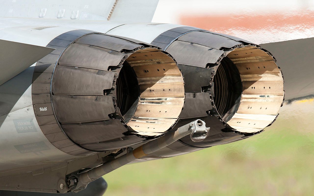
Figure 10.14:The nozzles of two General Electric f404 engines equipping a fighter aircraft. The geometry of the nozzle (not covered in this book) is programmed to adapt to the engine mass flow and whether or not afterburning is used.
Photo CC-by-sa by Peng Chen
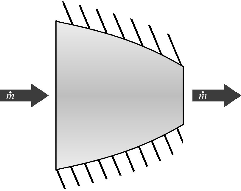
Figure 10.15:Schematic representation of a nozzle.
Diagram CC-0 Olivier Cleynen
In the case of an ideal nozzle, the expansion is isentropic, and we can relate the temperatures and just like in a turbine or a compressor, using the dreadful relations 4/36 to 4/38. Thus, knowing the inlet conditions and , for a given outlet pressure (atmospheric pressure), we can quantify the change in gas velocity:
Ideally, the nozzle expands the gases to ambient pressure and converts all the change in enthalpy of the gases into kinetic energy. In practice, of course, some of this energy is converted into heat due to friction. The efficiency of nozzles is quantified in a similar way to that of compressors and turbines, and is not studied in this book.

Finally, we note that the air intake of aeronautical engines often serves as a diffuser: the mirror opposite of a nozzle in function. It thus slows down the air and increases its pressure. On supersonic aircraft, a well-designed inlet can generate a compression ratio of 2, with a corresponding temperature increase.
10.5 Gas Turbine Configurations¶
10.5.1 Advantages of gas turbines¶
Within the realm of turbomachinery (machines which transfer power between a fluid and a rotating shaft), we call gas turbine the complete internal-combustion, turbine-powered machine, and not merely the component of the same name. The word “gas” here refers to the working fluid, not to the fuel, which may be any kind of combustible liquid or gas. Gas turbines have two major advantages over piston engines:
• The power-to-weight ratio of turbomachines is approximately three times higher, since the number of moving parts is reduced, and their movement is very simple, allowing them to be lighter;
• In air propulsion, the working fluid can be used as a medium of propulsion itself. It is sufficient to let the air exit the turbine with a residual pressure and let it expand in a nozzle. This generates a thrust by reaction (equal to the mass flow rate multiplied by its speed): this is the working principle of the jet engine.
Thus, gas turbines are used in applications where high power is required with significant weight or space constraints.
The major drawback of gas turbines is that their efficiency and responsiveness drop very quickly at low power levels. At partial load, the compression ratio and isentropic efficiency of turbines and compressors collapse, because it is hard to control fluid flow when the velocity of the rotor blades relative to stator blades is suboptimal. Gas turbines are therefore only useful in applications where high powers are required continuously. A gas turbine would be for example very poorly suited for road transport, because changes in power there are frequent and must be instantaneously acted on.
10.5.2 The gas generator¶
The heart of any gas turbine engine is called the gas generator. It contains only one shaft and one turbine (figure 10.16). This machine section has no use in itself, but the gases at its outlet, whose pressure is higher than at the inlet, can be used in a multitude of applications.
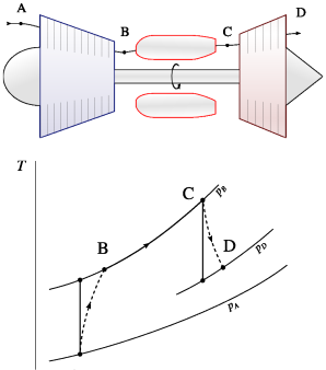
Figure 10.16:A “gas generator” (schematic drawing and temperature-entropy diagram). This machine has no interest in itself but has many derived applications. One of them is the turbocharger, for which a piston engine acts as the combustion
Schematic CC-by-sa Olivier Cleynen chamber, as described in §10.3.5. Diagram CC-0 Olivier Cleynen
In this configuration, the turbine extracts exactly enough power to power the compressor. At its outlet, the air is still compressed and can be used in a multitude of ways, as explored below.
10.5.3 Turbojet¶
The turbojet engine (figure 10.17) is the first application that has been made of a gas generator. At the outlet of the turbine, the air is expanded in a nozzle, which accelerates it and provides net thrust. It is the working fluid itself that is used to generate thrust.
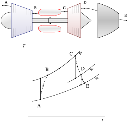
Figure 10.17:Turbojet (schematic and temperature-entropy diagram). At the outlet of the turbine, the air is still pressurized; it is expanded in a nozzle in order to be accelerated.
Diagram CC-by-sa Olivier Cleynen Diagram CC-0 Olivier Cleynen
Turbojet engines are extremely compact and mainly used in military aircraft.
10.5.4 Turboprop and turboshaft¶
Instead of using a nozzle as in a turbojet, it is possible to continue the expansion in the turbine until the gases reach atmospheric pressure. The power supplied by the turbine is then greater than the power supplied to the compressor.
This surplus work in the engine shaft can then be used to power a propeller (in the case of a turboprop) or an external element such as a generator or a pump (in the case of a turboshaft), as shown in figure 10.18. The cycle of these machines is sometimes called the Brayton cycle.
For a given engine mass flow, powering a propeller or the fan of a turbofan engine instead of merely expanding the gases in a nozzle increases thrust
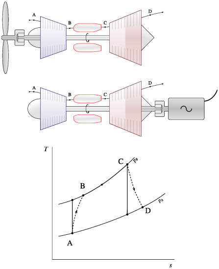
Figure 10.18:Schematics and temperature-entropy diagram of a turboprop (top) and a turboshaft engine (bottom). The power extracted by the turbine exceeds that absorbed by the compressor and is used to power the propeller or a generator.
Schematics CC-by-sa Olivier Cleynen Diagram CC-0 Olivier Cleynen
(this is quantified as the propulsive efficiency). The associated disadvantages are, of course, bulk and weight: the diameter of propellers and fans of modern engines often exceeds three meters, which translates into significant structural and mechanical constraints on the engine.
As for turboshaft engines, they find applications in helicopters, military ships, auxiliary electric generators, and gas turbine power plants. They are most often configured using the cycle modifications described in the following sections.
10.5.5 Turbofan¶
From a thermodynamic point of view, a turbofan (figure 10.19) is equivalent to a turboprop with a nacelle placed around it.
There are two separate air flows within a turbofan:
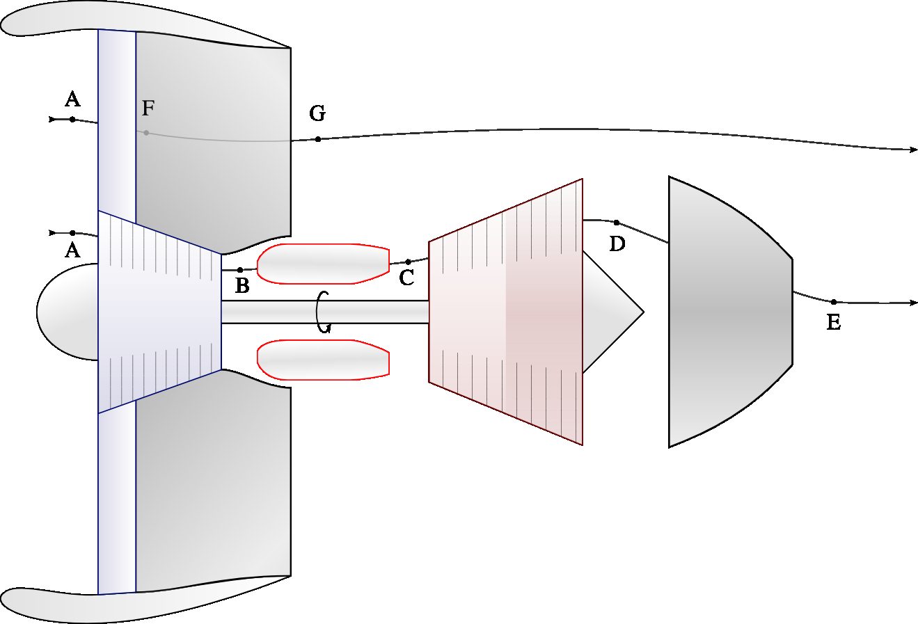
Figure 10.19:Schematic diagram of a turbofan. The engine’s thermodynamic core (A E) mechanically powers the fan, which allows the bypass flow (A G) to provide the majority of the thrust.
Diagram CC-by-sa Olivier Cleynen
• the core flow is the flow through the thermodynamic engine. After combustion, it passes through a turbine whose power far exceeds that of the compressor. This excess power is transferred to the fan;
• the bypass flow is lightly compressed by the fan and directly expanded in the nozzle surrounding the hot core of the engine. It is never heated. It is this “cold” air which makes for the majority of the thrust. It can be shown that the greater the ratio of bypass to core air flow (the bypass ratio), the more efficient the engine. The bypass ratio of modern engines is around 12.
10.5.6 Free turbine and multiple turbines¶
Depending on the applications, various arrangements of turbines and compressors can be used.
In a free turbine (also called free spool) configuration, the mechanical power supplied by the engine is transmitted by a dedicated turbine (figure 10.20). This allows each of the two shafts to be maintained at different speeds.
Since the speed of the turbine/compressor shaft is not constrained by the load imposed on the free shaft, it can operate at speeds closer to its optimum point and accelerate more easily. This advantage compensates for the increased mechanical complexity in applications such as helicopter engines, where significant power changes are sometimes required.
In a configuration with multiple spools, the compressor and turbine are each divided into several parts, thus forming two co-axial systems incorporated one into the other (figure 10.21).
The high-pressure turbine drives the high-pressure compressor (high-speed spool), and the low-pressure turbine drives the low-pressure compressor (low-speed spool).
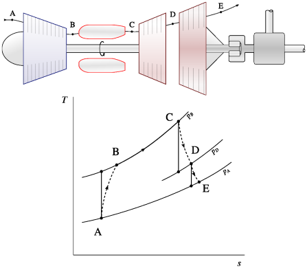
Figure 10.20:Turboshaft engine with a free turbine (schematic and temperature-entropy diagram). The power supplied by the engine comes exclusively from the free turbine.
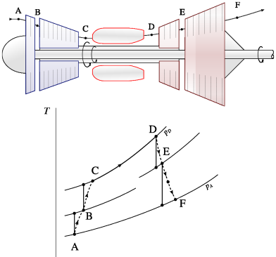
Figure 10.21:Twin-spool turboshaft engine (schematic and temperature-entropy diagram). The two shafts rotate at different speeds.
Schematic CC-by-sa Olivier Cleynen Diagram CC-0 Olivier Cleynen
Schematic CC-by-sa Olivier Cleynen Diagram CC-0 Olivier Cleynen
Just like for the free turbine, this arrangement allows each spool to operate at its own speed. Indeed, as the air pressure increases in the compressor, its density and temperature also increase. This configuration allows the blades to be operated at higher speeds, thus reducing their size.
10.6 Modification of Gas Turbine Cycles¶
10.6.1 Intercooling and reheat¶
It is sometimes desirable to increase the work ratio and specific power, even at the cost of a decrease in total efficiency, as mentioned in §10.2 above.
In order to reduce the power absorbed by the compressor, intercooling is sometimes used. The compression is interrupted and the air is cooled before the compression process is completed (figure 10.22).
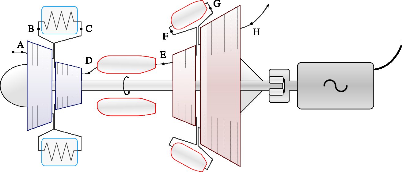
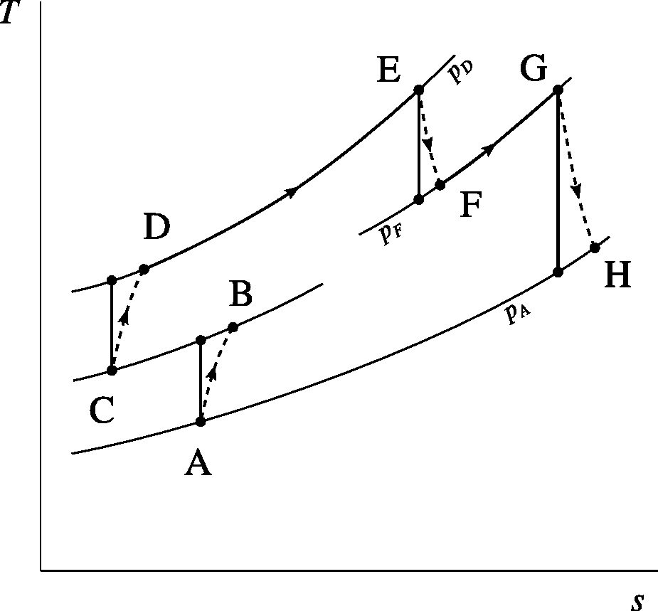
Figure 10.22:A turboshaft generator with intercooler and reheat system (schematic and temperature-entropy diagram). The intercooler cools the air in the midst of compression;while the second combustion chamber reheats the gases in the midst of the expansion. The two modifications are independent of each other and each can be installed alone.
Schematic CC-by-sa Olivier Cleynen Diagram CC-0 Olivier Cleynen
The compression of a gas between two given pressures imposes a ratio between the initial and final temperatures (4/36). On the other hand, the power required to compress a gas between these two pressures depends on the difference between these two temperatures (10/6). Therefore, the lower the initial temperature, the lower the power required to reach a given pressure.
In the same vein, we can increase the specific power supplied by the turbine by carrying out a second combustion with the gases before the end of the expansion: this is called reheat. The process is similar to the reheating of steam in steam power plants (§9.4.4 p. 256).
It will not have escaped the student that the efficiency is inevitably reduced by the use of intercooling. Indeed, the combustion chamber must supply more heat, at a lower average temperature. This reduction in efficiency will be balanced against the reduction in the size of the compressor (usually the largest component of an engine) and the increase in specific power. Intercooling and reheat are typical of machines where the power-to-size ratio must be maximized.
In order to partially offset the loss of efficiency in stationary engines, it is sometimes possible to recover heat from the exhaust gases and use it to heat the air at the compressor outlet, thus relieving the combustion chamber. The heat exchanger is sometimes called an economizer (figure 10.23); it is left to the student to trace the cycle followed on a temperature-entropy diagram and to find the conditions required for its operation.
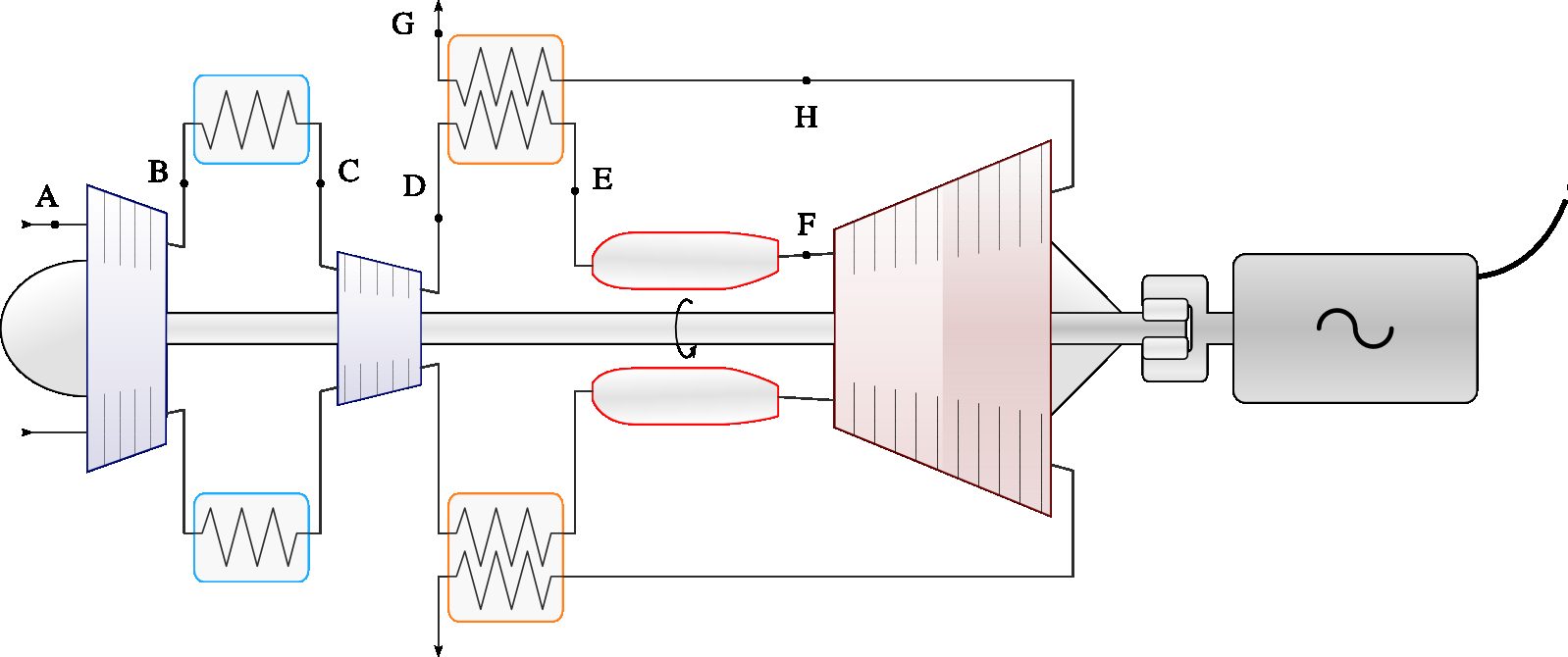
Figure 10.23:Turboshaft generator with an intercooler and an economizer heat exchanger. The exhaust gases are redirected inside the engine to supply heat to the gases at the entrance of the combustion chamber. It is left to the student to determine the limits of the process.
Diagram CC-by-sa Olivier Cleynen
10.6.2 Afterburning¶
Afterburning (or reheat in British English) is the addition of a second combustion phase in a jet engine, downstream of the turbine and upstream of the nozzle (figure 10.24). The principle is exactly the same as that of reheat: increase the specific thrust of the machine (at the expense of its efficiency).
Like reheat, afterburning alters the properties (specific volume in particular) of the gases and requires resizing of downstream components. The geometry of the nozzle is adapted according to whether the post-combustion is active or not. Adding an afterburner system to a turbojet engine merely requires the installation of burners and a system for varying the geometry of the
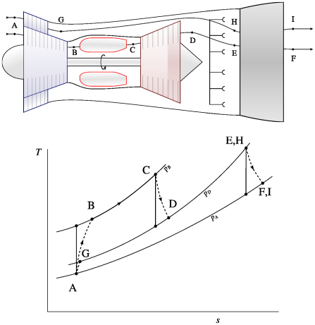
Figure 10.24:Afterburner on a dual-flow turbojet engine (schematic and temperature-entropy diagram). States E and H are not necessarily merged in practice.
Diagram 1 CC-by-sa*, Diagram 2* CC-0 Olivier Cleynen nozzle. The increase in weight is low compared to the increase in available power.
The outrageous loss of efficiency caused by the use of afterburners, as well as the deafening levels of noise and pollution they generate, limit their use to the military sector (especially on combat aircraft).
10.6.3 Turbine cooling¶
Because an increase in combustion temperature increases efficiency and specific power, engine designers are driven to develop technologies to maximize the temperature at the outlet of the combustion chamber (tet, for turbine entry temperature).
One of the strategies used is to cool the turbine with bleed air from the compressor (figure 10.25). The bleed air is passed through the turbine blades themselves, allowing for an increase in combustion temperature without risking damage to the blades. The most efficient and advanced cooling systems wrap the turbine blades with this cooler air. This allows, in modern engines, the tet temperature to exceed the melting temperature of the blades by more than , or !
Such turbine cooling comes at a significant cost. First, in a real engine, less work is recovered from the expansion of this bleed air than was required for its compression (in the limiting case where compression and expansion
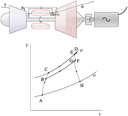
Figure 10.25:Turbine cooling using air taken from the compressor (schematic and temperature-entropy diagram). This air, at moderate temperature, bypasses the combustion chamber and never comes into contact with the fuel. Here the represented engine is a turboshaft, but turbine cooling can be used in any configuration.
Schematic CC-by-sa Olivier Cleynen Diagram CC-0 Olivier Cleynen are isentropic, this energy cost is zero). The circulation of this air therefore represents a burden that must be offset by the increase in efficiency it generates. Secondly, the compressor and the turbine must be oversized to accommodate a larger air flow.
Turbine cooling is a major research area in aeronautical propulsion. Techniques from a handful of fields (materials, fluid mechanics, mechanical design, combustion chemistry) are combined there in order to improve the thermodynamics of the engines.
On twin-engine aircraft qualified for etops flights, each engine must be able to alone maintain the aircraft flying while supplying many systems (pressurization, de-icing, heating, electrical and pneumatic generation) for several hours with demonstrated reliability.
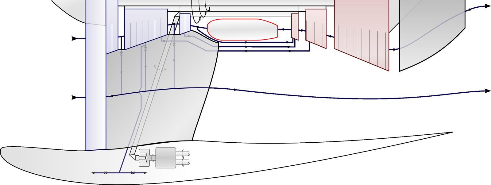
Figure 10.26:Thermodynamic circuit of a modern turbofan engine. The machine combines multiple spools, mechanical and pneumatic power extractions, compressor bleeds for turbine cooling, and two main air flows. It is left to the student to trace the cycle on a temperature-entropy diagram.
Problems¶
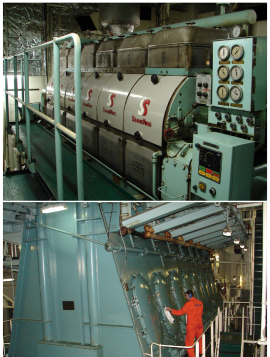
Figure 10.32:The two Diesel engines of a oil tanker: a six-cylinder generator (top) and a seven-cylinder propulsion engine (bottom).
What is the gas temperature at the end of the combustion?
What is the maximum pressure reached in the engine?
What is the temperature at the end of the expansion?
What is the engine cycle efficiency?
It is easy to show that at the same compression ratio, a Diesel cycle is less efficient than a so-called “gasoline” cycle (Otto cycle). Why is it used nevertheless?
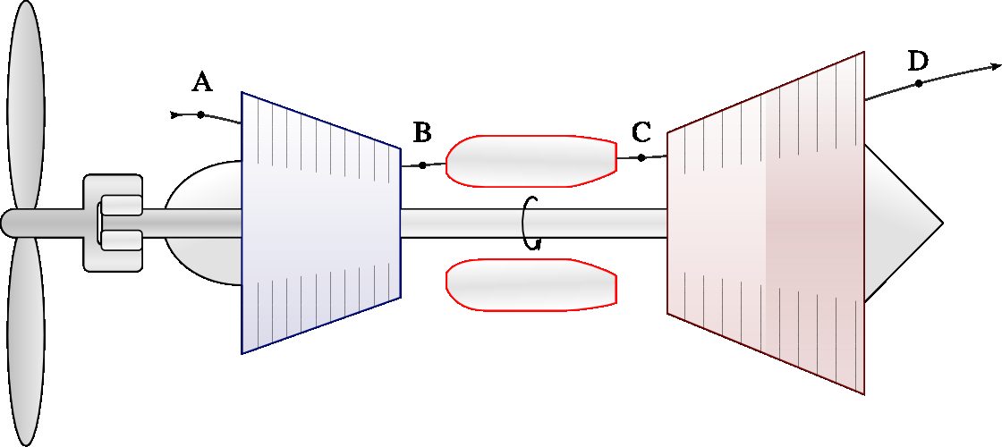
Figure 10.33:Internal arrangement of a turboprop.
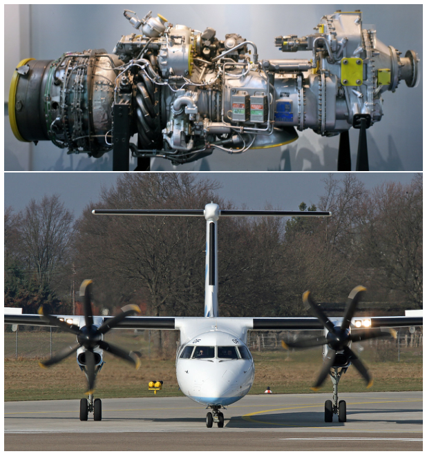
Figure 10.34:A Pratt & Whitney Canada pwc123 turboprop engine powering a BombardierDash 8. The pwc123 is configured with three concentric rotating assemblies, with the engine shaft powered by a free turbine, but its operation principle remains similar to that described in figure 10.33.
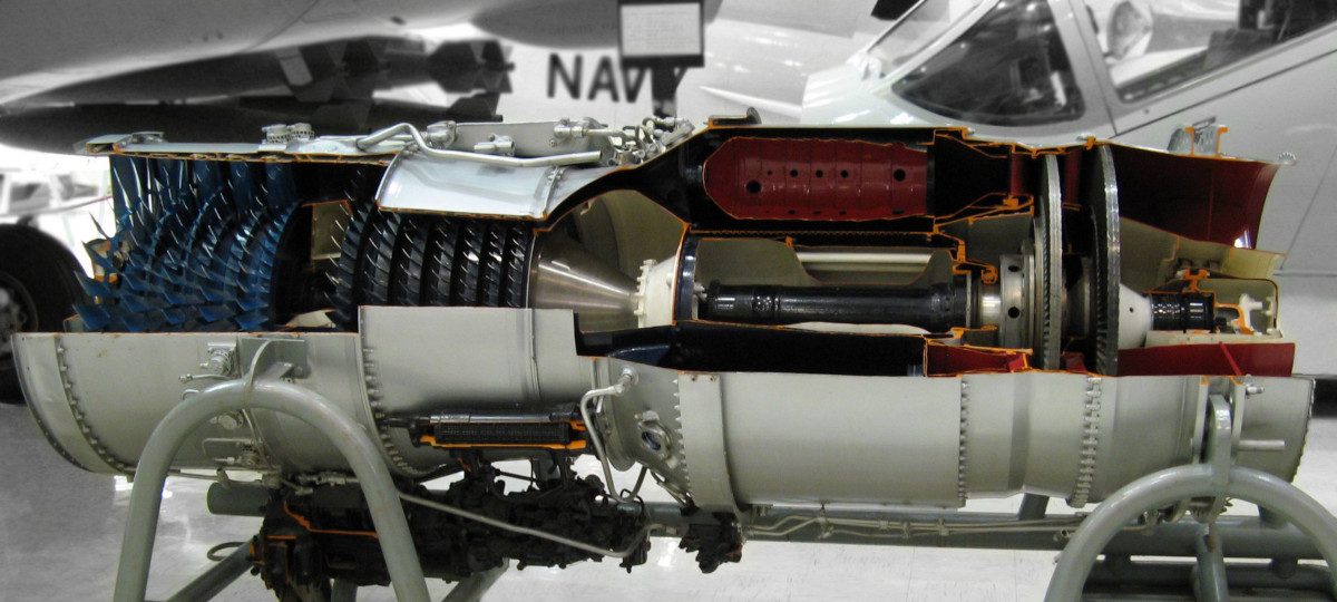
Figure 10.35:A turbojet with twin spools Pratt & Whitney j52 (or jt8a), built in 4500 units. It still equips the ea-6b Prowler.

Figure 10.36:Cutaway diagram of a General Electric cf6-6. The engine propelled all major long-haul aircraft families of the 1970s and 1980s.
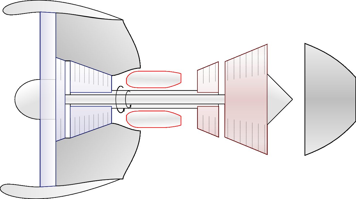
Figure 10.37:Schematic diagram of the arrangement of the General Electric cf6.
Draw the new thermodynamic cycle on the pressure-volume diagram above, qualitatively.
What is the increase in net power?
What is the new work ratio?
What is the new efficiency?
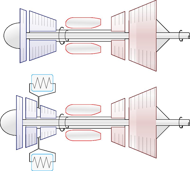
Figure 10.38:Top: schematic diagram of a turboshaft based on the cf6 from which the fan has been removed. Bottom: the same turboshaft engine modified by the addition of an intercooling system.
Diagrams CC-by-sa Olivier Cleynen