After the treatment in the preceding chapter of the laws of Gaussian geometrical optics, more complex systems based on lenses and reflectors can now be considered.
1The Camera Obscura
The camera obscura or pinhole camera is the simplest image forming system. It consists of a closed box with a pinhole on one side. An inverted image is cast on the opposite side of the box as shown in Figure 1. If the hole is too large, the image is very blurred. At the cost of less light, the image can be made sharper by reducing the aperture. The camera obscura can have a wide angular field and can keep objects over a large range of distances acceptably sharp (great depth of field), as in the right picture of Figure 1. If a film is used to record the image, long exposure times are often needed because only a small amount of light enters the pinhole. Some artists have used a camera obscura as a drawing aid.
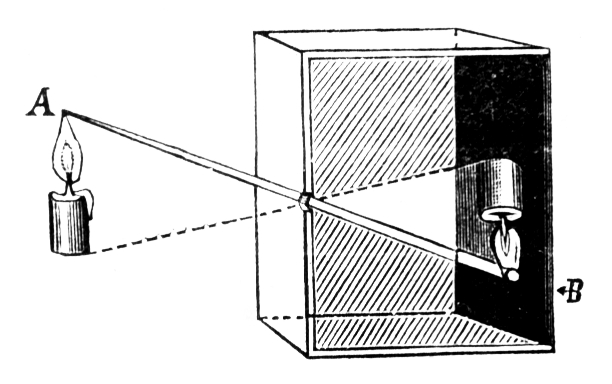
Figure 1:The principle of the camera obscura (from Wikimedia Commons in Fizyka z. (1910) / Public Domain). Contemporary examples of camera obscura photography can be found in the work of Abelardo Morell.
2The Camera
In Figure 2 a single-lens reflex (SLR) camera is shown. The name means that the photographer views the scene through the same objective used to take the picture; an objective can contain several lens elements. Light passes through an adjustable iris diaphragm that controls the -number. In the viewing position, a mirror tilted at about directs light through a prism to the viewfinder. During exposure the mirror swings up, the diaphragm reaches its selected opening, and light reaches the image sensor. Focusing changes the position of one or more lens elements. Cameras may determine focus by contrast detection, phase detection, or a combination of methods.
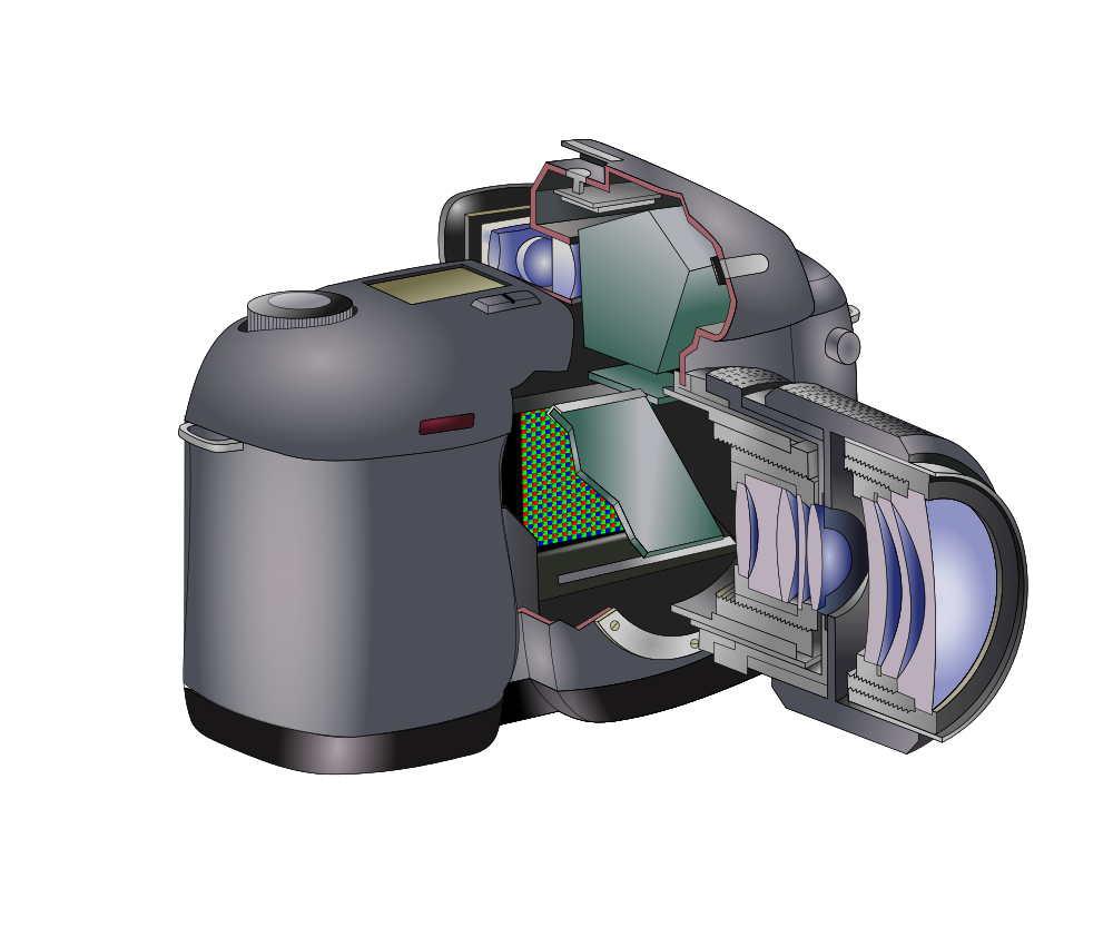
Figure 2:Digital SLR camera. The pixelated digital sensor is behind a movable mirror at an angle of 45 degrees with the optical axis. (from Wikimedia Commons by Jean François WITZ / CC BY-SA 3.0).
The angular field of view (AFOV) is defined for scenes at large distances and is approximately the angle subtended by the sensor at the image-side principal plane when the image distance is the focal length (Figure 3). For a fixed sensor size, AFOV decreases as increases. For example, a 50 mm lens on a 36 mm-wide sensor has a horizontal field of view of about .
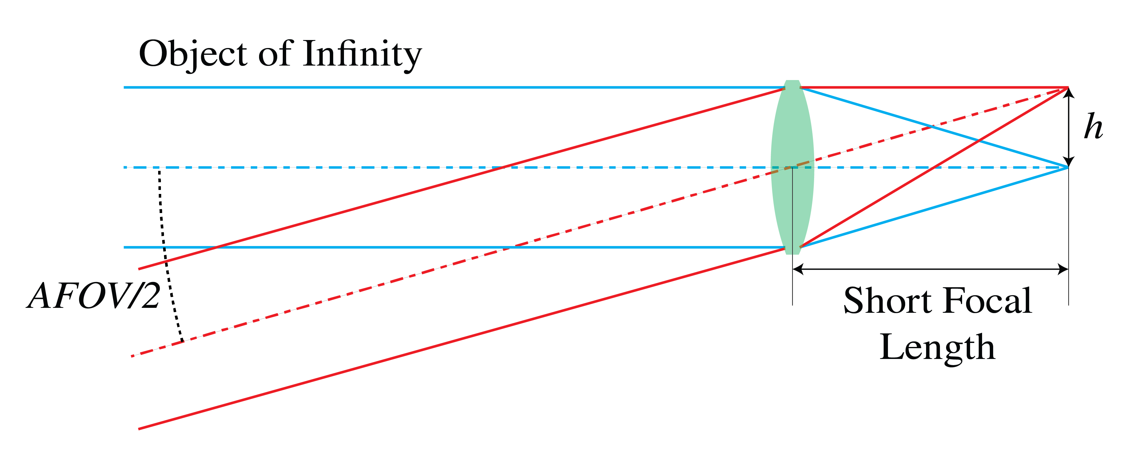
Figure 3:Angular field of view of a camera.
More complex systems can have a variable focal length by changing the distance between the lenses, i.e. they are able to zoom into a scene.
The depth of field is a range of object distances around a given distance for which the images on the sensor are sharp. The depth of field depends on the diaphragm. When the aperture is wide open, rays forming the image will make larger angles with the optical axis. With a large diaphragm, rays from objects at various distances produce more blurred images on the sensor (see Figure 4). When the aperture is reduced, this effect is less and therefore a smaller diaphragm implies a larger depth of field. The drawback is that less light reaches the sensor; therefore, a longer exposure time is needed.
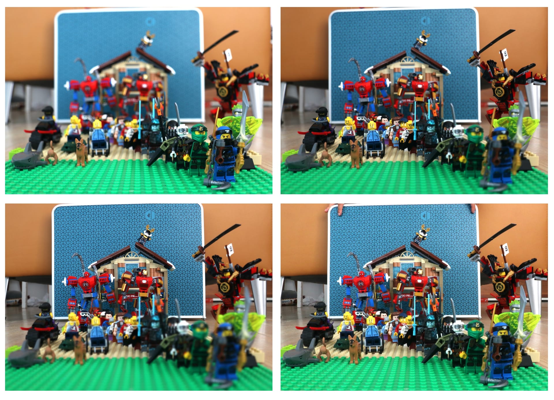
Figure 4:Four images taken with different diaphragm settings and different focal planes. The image on the bottom right is taken with a small diaphragm and the entire image appears clear (photos taken by Aurèle J.L. ADAM / CC BY-SA).
3Camera in a Smartphone
A smartphone camera typically combines a compact objective with several lens elements, often including aspheric surfaces, and an electronic image sensor. Its short focal length and small sensor produce a wide field of view in a thin package.
Autofocus changes the position of lens elements to place the subject image on the sensor. Contrast detection evaluates image sharpness, while phase detection estimates the direction and size of a focus error from separated views of the scene. Some cameras also use a time-of-flight sensor to estimate subject distance from the delay of reflected light. Image processing can combine exposures and reduce noise, but it cannot recover arbitrary detail lost to severe defocus.
4The Human Eye
The eye is an adaptive imaging system.
4.1Anatomy
The eyeball is roughly 24 mm long. Its interior is largely filled by the transparent, gel-like vitreous humor (refractive index about 1.337), and its outer white coat is the sclera (Figure 5). The transparent cornea forms the curved front surface of the eye; its refractive index for green light is about 1.376. Much of the eye’s refracting power comes from the air–cornea interface, which loses power under water because water and cornea have more similar refractive indices.
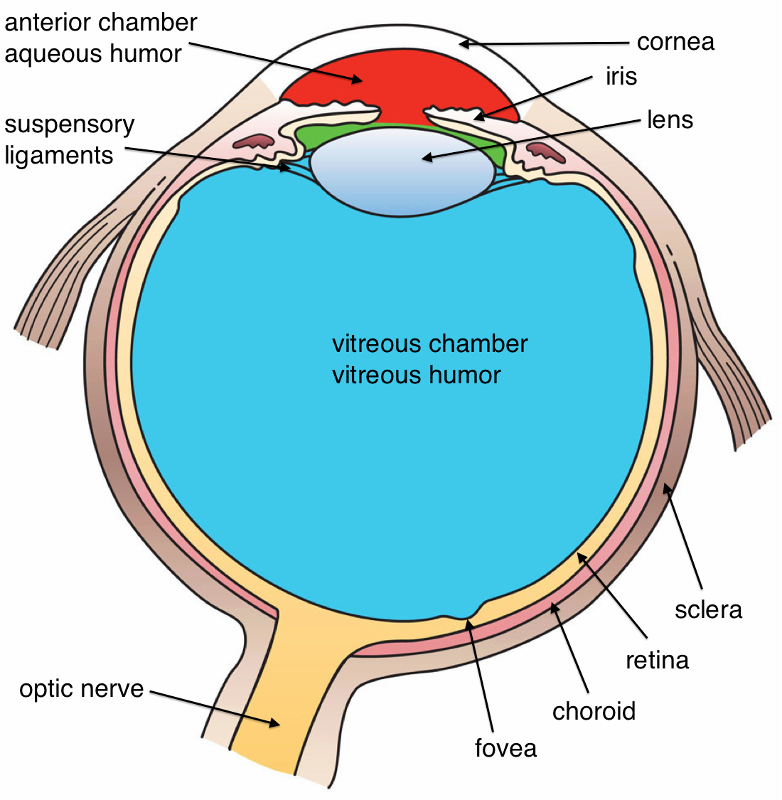
Figure 5:Cross section of a human eye (from Wikimedia Commons by Holly Fischer / CC BY).
After passing through the cornea, light crosses the aqueous humor () and enters the pupil, the opening in the colored iris. The iris changes pupil diameter to regulate the amount of light entering the eye. Behind the iris is the flexible crystalline lens, about 9 mm across and 4 mm thick when relaxed. Its refractive index varies across the lens; accommodation changes its shape and optical power.
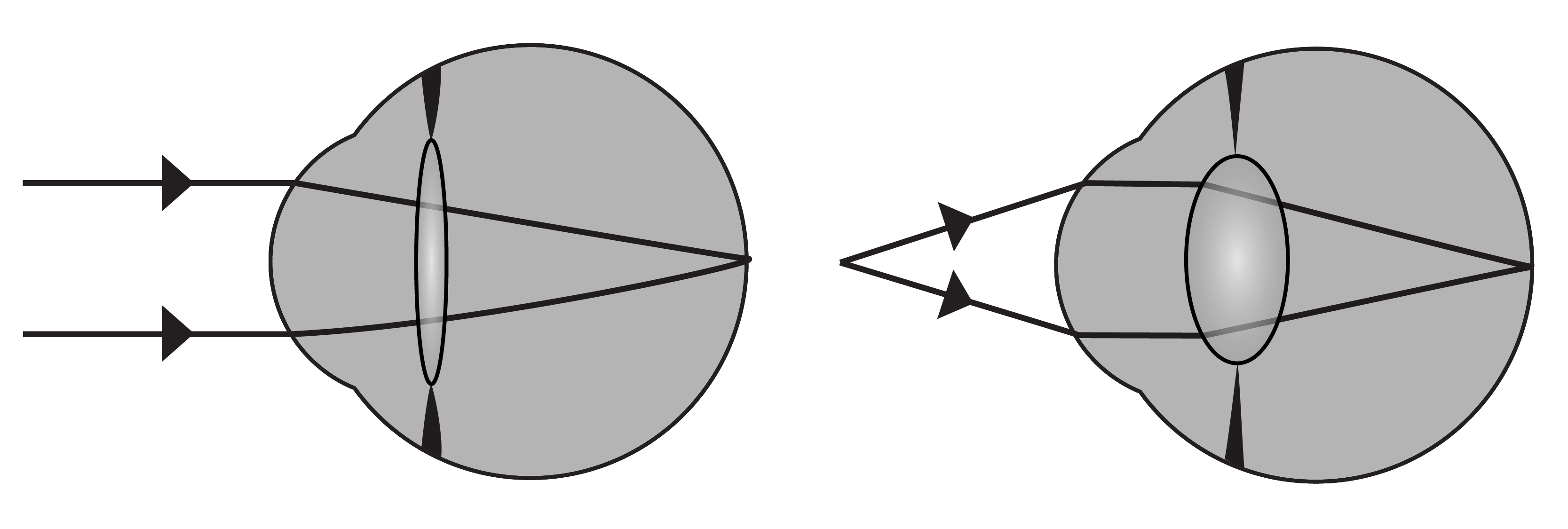
Ray diagrams of the eye focusing distant and nearby objects on the retina.
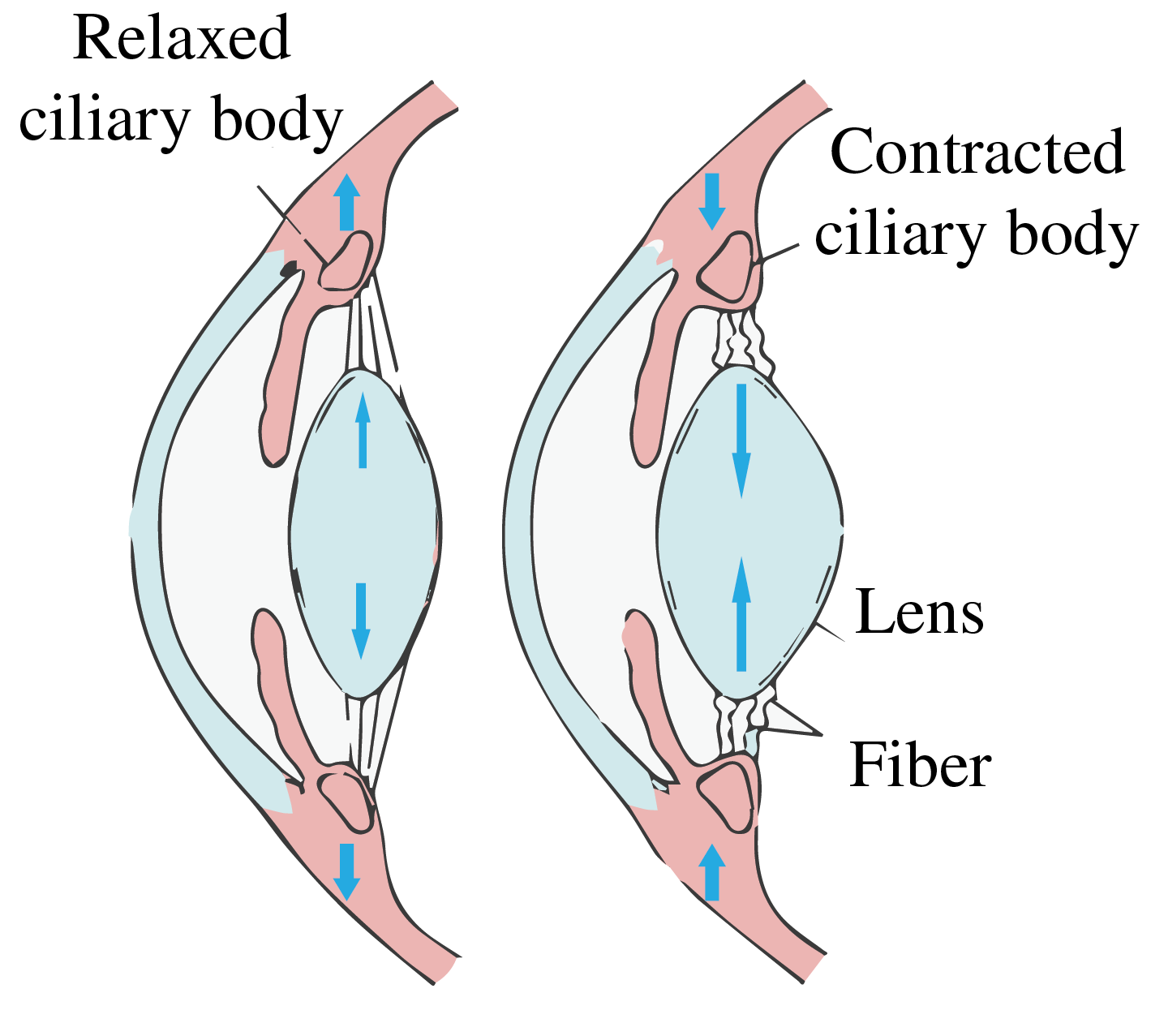
Figure 7:Accommodation changes the shape of the crystalline lens: the ciliary muscle is relaxed at left and contracted at right. Adapted from Sjaastad O.V., Sand O. and Hove K. (2010), Physiology of Domestic Animals, 2nd ed., Scandinavian Veterinary Press.
4.2Working of the eye
The cornea and crystalline lens form a compound optical system. For a first approximation, we replace them with one effective thin lens near the front of the eye. This simplified model neglects the separation of the eye’s refracting surfaces.
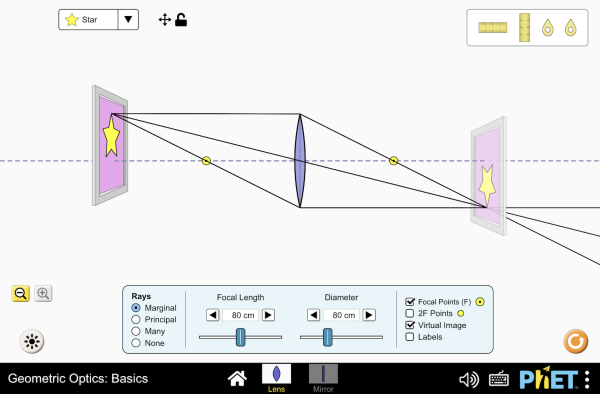
Figure 8:A single thin lens with object and image distances under control. Treat it as the one-lens model of the eye used below: move the object inside and outside the near point and watch the image distance respond the way accommodation must.
Interactive simulation: Geometric Optics Basics
In this model, the relaxed eye focuses rays from infinity on a retina 24 mm behind the effective lens, so its image-side focal distance is mm. With air on the object side and vitreous humor on the image side, the focal distances differ. The power and signed object-side focal distance are (see the thin-lens matrices in the Ray Matrix chapter):
When an object moves closer, the ciliary muscle contracts, allowing the crystalline lens to become rounder and increasing the eye’s optical power, as shown at the right of Figure 7. At a certain point, the object will be too close to be focused on the retina. This is called the near point of the eye. The near point generally moves farther away with age as the crystalline lens becomes less flexible. In calculations of angular magnification, 25 cm is a conventional reference viewing distance, not a fixed physiological near point. The far point is the furthest object imaged sharply on the retina by the relaxed eye; for an emmetropic eye it is at infinity.
4.3Retina
The retina contains two principal types of photoreceptor: rods, which are highly sensitive in dim light, and cones, which support color vision and fine detail in brighter light. The fovea centralis has a high density of cones and provides the sharpest central vision. Visual signals travel to the brain through the optic nerve. The point where the optic nerve exits the retina has no photoreceptors and creates a blind spot.
4.4Dioptric Power of a lens
For a single lens the dioptric power is defined by:
with and the radii of the thin lens measured in meters, is the index of refraction of the lens and that of the ambient medium. (When the media to the left and right of the lens are different, the refractive index to the right of the lens and the right focal distance should be taken). For two lenses in contact, the focal length is given by:
hence the combined power of the two lenses in contact is the sum of the individual powers:
A positive thin lens of focal length cm in air has power D. If it is in contact with a thin negative lens of power D, the combined optical power is zero: collimated incident rays remain collimated in the thin-lens approximation.
4.5Eyeglasses
The eye can suffer from imperfections as seen in Figure 9. We discuss the most common imperfections and their solutions.
a. Myopia or nearsightedness. A myopic eye has focal distances that are too short (has too high power). Distant objects are focused in front of the retina by the relaxed eye. The far point is thus not at infinity, but closer. This can be corrected by a negative lens. Suppose the far point is at 2 m. If a correcting lens is placed close to the cornea, it must form a virtual image of a distant object about 2 m in front of the eye. The thin-lens imaging equation in air, with and m, gives the approximate required power:
For eyeglasses held away from the cornea, the required power changes with vertex distance, the separation between the lens and the eye. The value above assumes negligible separation.
Because a contact lens sits close to the cornea, adding its power to the eye’s effective power is a useful first approximation.
b. Hyperopia or farsightedness. In this case a distant object is imaged by the relaxed eye behind the retina, i.e. the back focal distance of the relaxed eye is larger than the depth of the eye. Close objects cannot be imaged on the retina; hence, the near point is relatively far from the cornea. In order to bend the rays more, a positive lens is placed in front of the eye. Suppose that a hyperopic eye has a near point at a distance of 125 cm. For an object at the 25 cm reference distance cm to have a virtual image at cm, so that it can be seen, the focal length of the positive lens must satisfy
hence the power must be diopter.
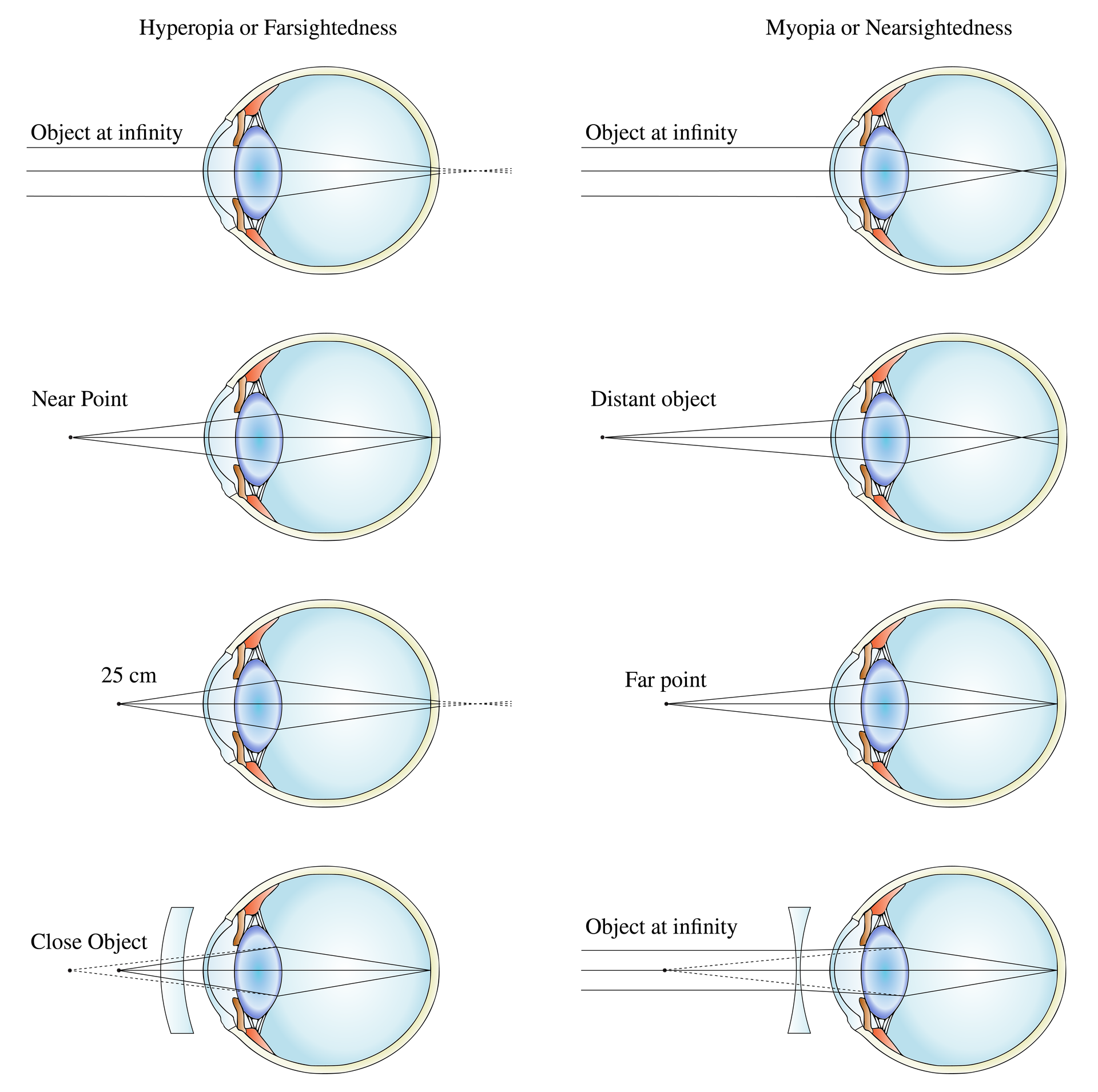
Figure 9:Correction of farsighted (left) and nearsighted (right) eyes (adapted from Wikimedia Commons by Gumenyuk I.S. / CC BY-SA 4.0).
c. Presbyopia. Presbyopia is an age-related reduction in accommodation that moves the near point farther from the eye. Reading glasses, bifocals, or progressive lenses can supply the extra power needed for near tasks.
d. Astigmatism. In this case the focal distances for two directions perpendicular to the optical axis are different. It is attributed to a lack of symmetry of revolution of the cornea. This is compensated by using glasses which themselves are astigmatic.
4.6New Correction Technique
In recent years, to correct eye defects such as myopia and astigmatism, technology has been developed to change the local curvatures of the surface of the cornea using an excimer laser. The laser is computer-controlled and causes photo-ablation in parts of the cornea.
5Magnifying Glasses
A magnifying glass produces a larger retinal image than unaided viewing at the conventional reference distance cm. Bringing an object closer to the eye also increases its angular size, but accommodation limits how close it can be while remaining sharp. A positive lens can place a magnified, upright virtual image at a comfortable viewing distance or at infinity. An example is given in Figure 10.
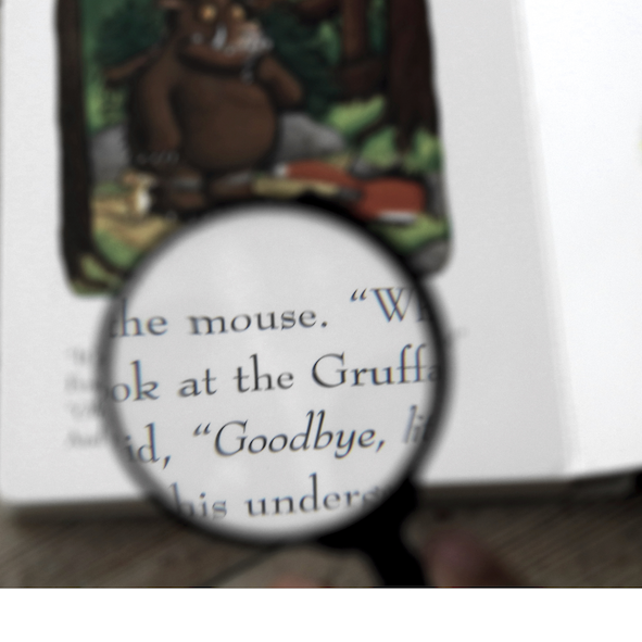
Figure 10:Example of a positive lens used as a magnifying glass (picture taken by A.J.L. Adam / CC-BY-SA 4.0).
5.1Magnifying Power
The magnifying power or angular magnification is defined as the ratio of the size of the retinal image obtained with the instrument to the size of the retinal image as seen by the unaided eye at normal viewing distance . To estimate the size of the retinal image, we compare in both cases where the chief ray through the top of the object and the center of the pupil of the eye hits the retina. Since the distance between the eye lens and the retina is fixed, the ratio of the image size on the retina for the eye with and without a magnifying glass is:
where and are the angles between the optical axis and the chief rays for the aided and the unaided eye, respectively, as shown in Figure 11. Working with these angles instead of distances is in particular useful when the virtual image of the magnifying glass is at infinity. Using and with and positive and the positive distance from the virtual image to the eye, we find
Since and we have,
where we used the lens equation for the magnifying glass. We have , where is the distance between the magnifying glass and the eye. Hence, Eq. (8) becomes:
where is the power of the magnifying glass.
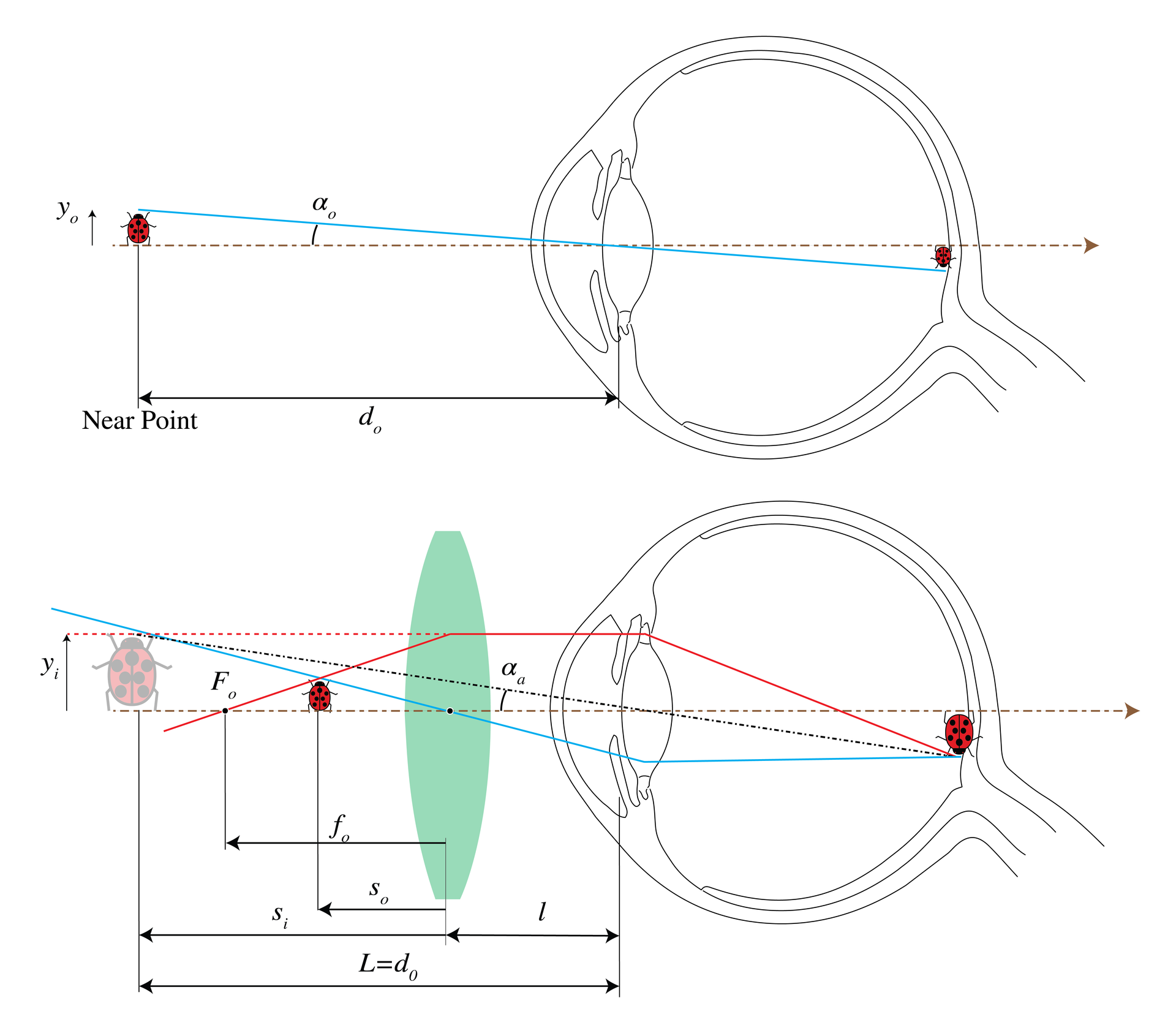
Figure 11:An unaided view (top) and an aided view using a magnifier.
We distinguish three situations:
: the magnifying power is then .
and the virtual image is at the 25 cm reference distance, : the magnifying power is
The object is at the focal point of the magnifier (), so that the virtual image is at infinity () and hence
for every distance between the eye and the magnifying glass. The rays are parallel, so that the eye views the object in a relaxed way. This is the most common use of the magnifier.
For a 10 D magnifier and cm, the relaxed-eye value is , while placing the lens close to the eye and viewing a virtual image at 25 cm gives . The difference becomes relatively smaller for stronger magnifiers.
5.2Nomenclature
Magnifiers are commonly labeled by their magnifying power when the final image is at infinity (case 3 above). For example, a 10 D magnifier has , or , relative to unaided viewing from the 25 cm reference distance.
6Eyepieces
An eyepiece or ocular is a magnifier used before the eye at the end of another optical instrument such as a microscope or a telescope. The eye looks into the ocular and the ocular “looks” into the optical instrument. The ocular provides a magnified virtual image of the image produced by the optical instrument. Similar to the magnifying glass, the virtual image should preferably be at or near infinity to be viewed by a relaxed eye. A simple eyepiece can contain:
the field lens, which is the first lens in the ocular;
the eye lens, which is closest to the viewer. The eye relief is the distance from the last eyepiece surface to the exit pupil, where the eye should be placed to see the full field. A field stop limits the angular field of view, while an aperture stop limits the cone of rays admitted from each object point. An example is given in Figure 12.
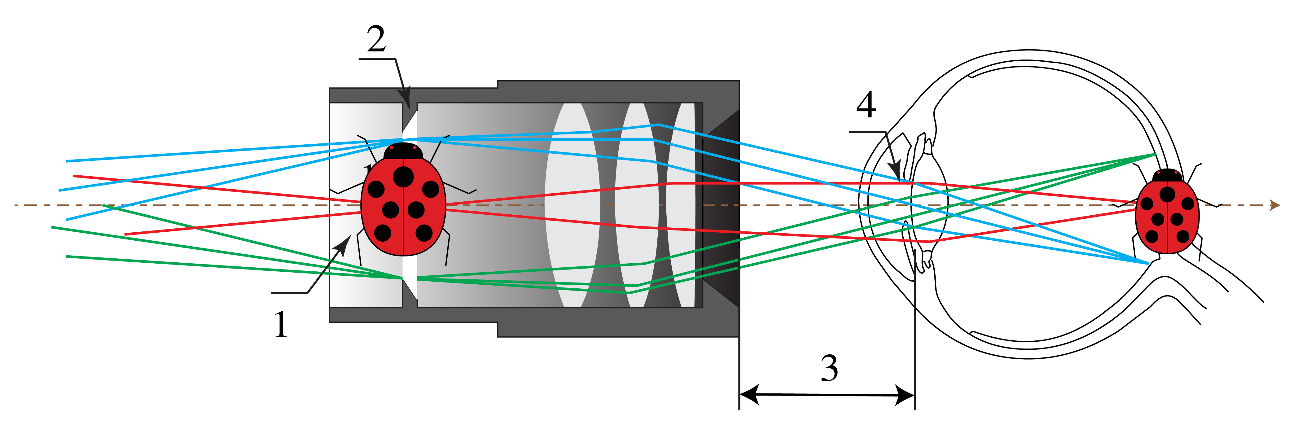
Figure 12:Example of an eyepiece consisting of three lenses. 1) Real image, 2) field diaphragm, 3) eye relief, 4) eye pupil (adapted from Wikimedia Commons by Tamas-flex / CC BY-SA 3.0).
7The Compound Microscope
A magnifier alone can provide very high magnification only at the cost of intolerable aberrations. The compound microscope is a magnifier of close objects with a high angular magnification, generally more than . It was invented by Zacharias Janssen in Middelburg in 1590 (but this claim is disputed). The first element of the compound microscope is an objective (in Figure 13 a simple positive lens) which makes a real, inverted and magnified image of the object in the front focal plane of an eyepiece (where there is also the field stop). The eyepiece will make a virtual image at infinity, as explained above.
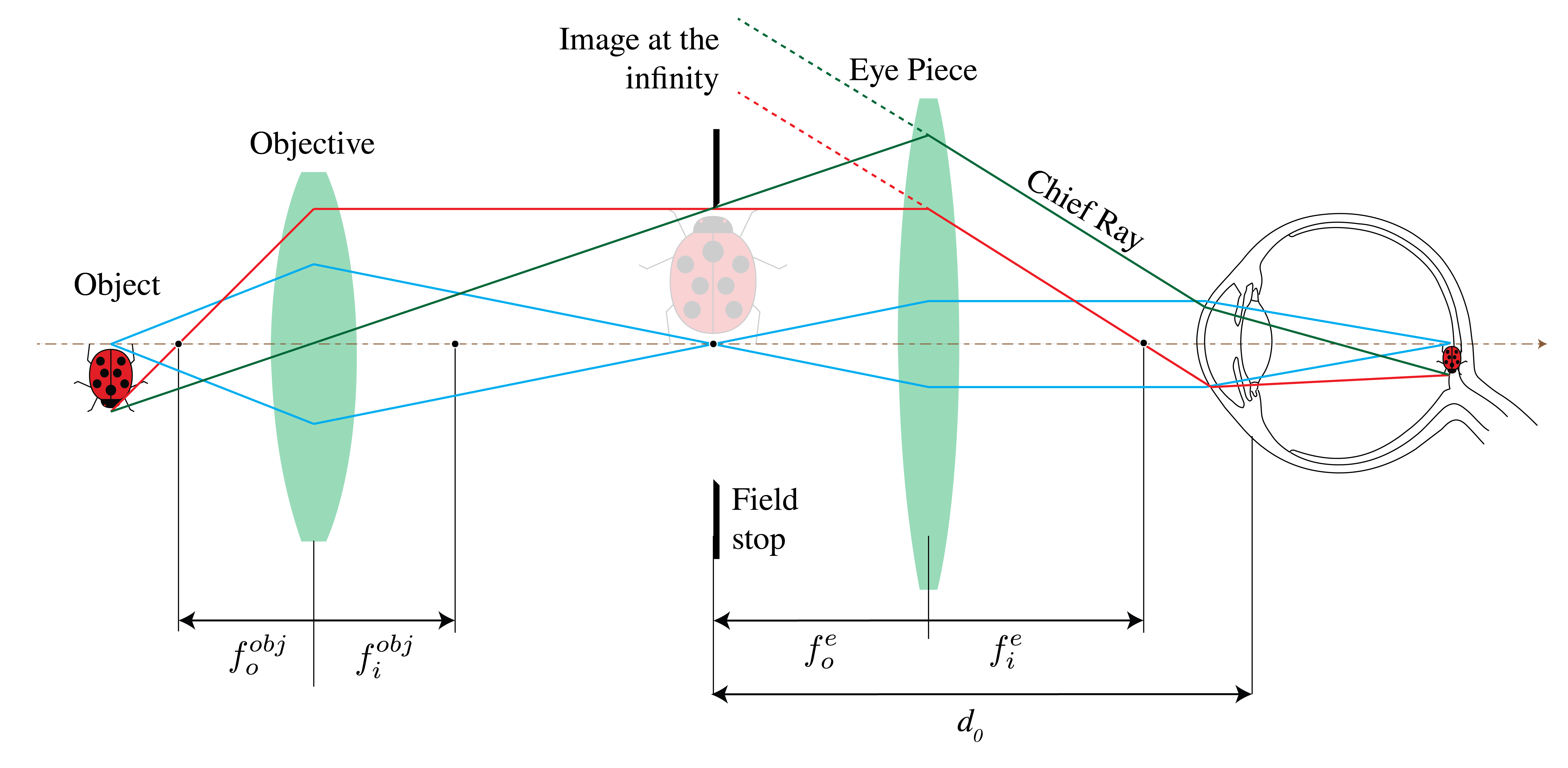
Figure 13:Simple compound microscope. The objective forms a real image of a nearby object. The eyepiece enlarges this intermediate image. The final image can be bigger than the barrel of the device, since it is virtual.
The magnifying power of the entire system is the product of the transverse linear magnification of the objective and the angular magnification of the eyepiece :
According to the transverse magnification equation (see the Ray Matrix chapter): , where is the distance from the objective’s back focal plane to its image plane and is the objective focal length. In the finite-tube model shown, is the optical tube length: the distance between the objective’s back focal point and the eyepiece’s front focal point. A traditional finite-tube example uses cm; infinity-corrected microscopes have a different optical layout. Furthermore, according to Eq. (12), the angular magnification for a virtual image at infinity is: . Hence, we obtain:
where cm is the reference viewing distance and all lengths use the same units. For example, a objective combined with a eyepiece gives total magnification.
The numerical aperture of a microscope is a measure of the capability to gather light from the object. It is defined by:
with the refractive index of the immersing medium, usually air, but it could be water or oil, and the half-angle of the maximum cone of light accepted by the lens. The numerical aperture is the second number etched in the barrel of the objective. It ranges from 0.07 (low-power objectives) to 1.4 for high-power objectives. Note that it depends on the object distance. In Scalar Diffraction Optics it will be explained that is, for a given object distance, proportional to the resolving power; the resolution is the minimum transverse distance between two object points that can be resolved in the image.
8The Telescope
A telescope enlarges the retinal image of a distant object. Like a compound microscope, it is also composed of an objective and an eyepiece as seen in Figure 14.
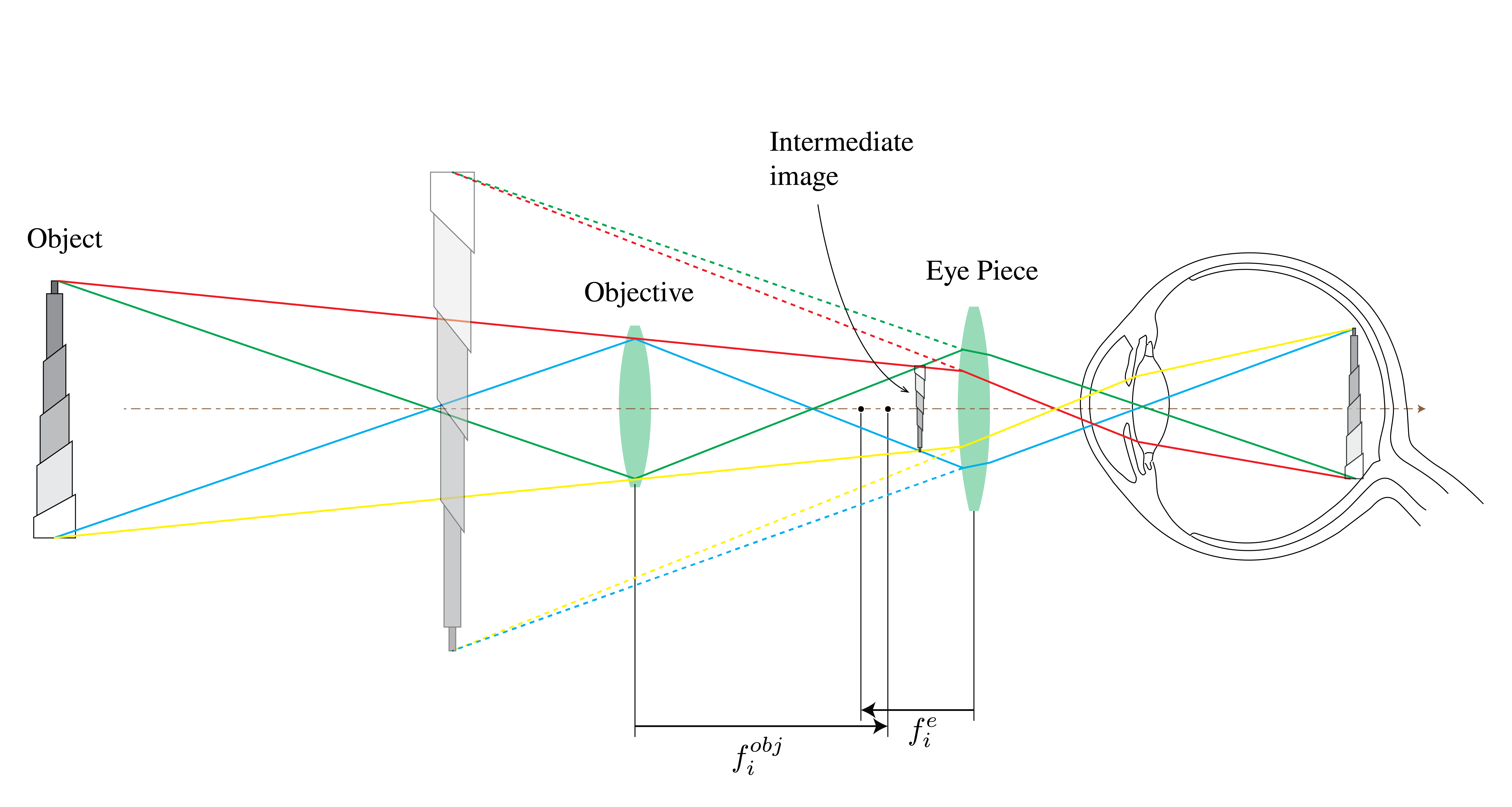
Figure 14:Keplerian astronomical telescope.
The objective forms a real intermediate image of a distant object near its back focal plane. If that intermediate image lies at the eyepiece’s front focal plane, the emerging rays are parallel and the eye can view the final image while relaxed. The final image is inverted. For objects at a large but finite distance, the objective’s image lies just beyond its back focal point and the eyepiece position must be adjusted slightly to retain relaxed viewing.
As seen earlier, angular magnification is , where is the small angle subtended by the distant object at the unaided eye and is its apparent angle through the telescope. For an object at infinity, the ray triangles in Figure 15 give
(The minus sign is because the image is inverted.)
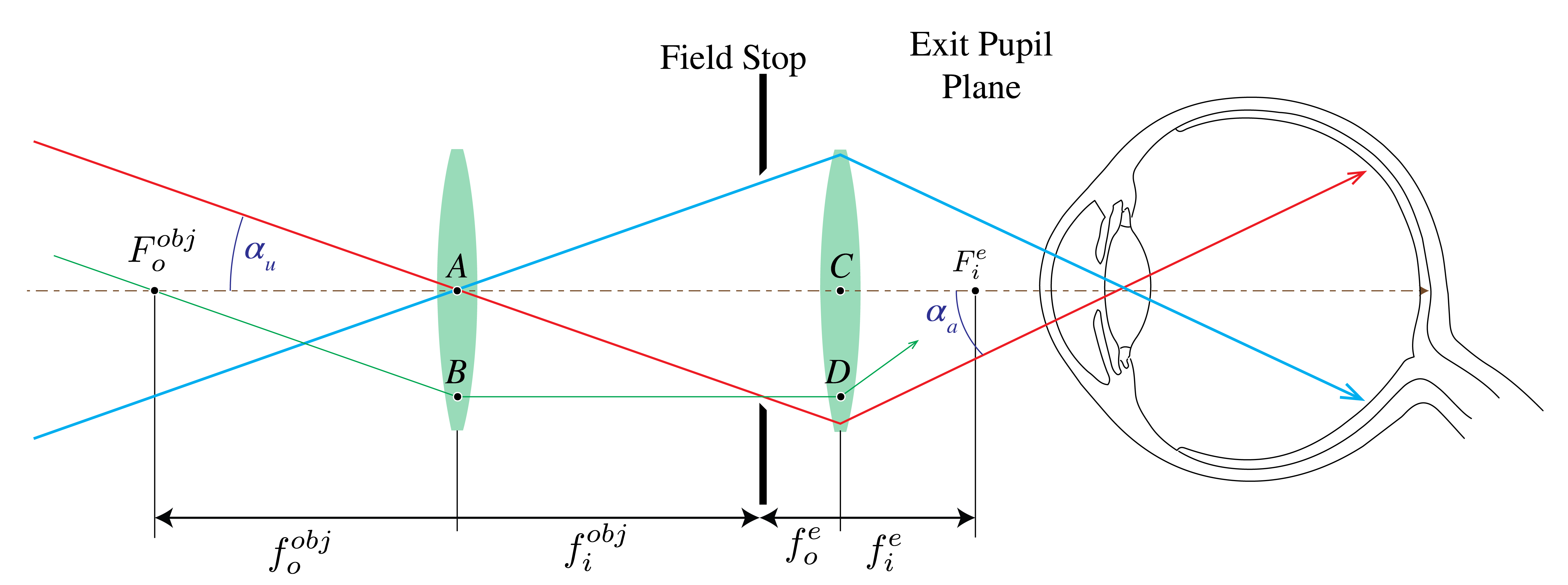
Figure 15:Ray angles for a telescope.
9Chapter Summary
The camera uses a lens to form a real, inverted image on film or a sensor; exposure is controlled by the f-number and shutter speed.
The human eye is a variable-focus optical system where accommodation changes the lens power to focus objects at different distances.
Vision defects: Myopia (nearsightedness) is corrected with negative lenses; hyperopia (farsightedness) with positive lenses.
The magnifying glass produces a magnified virtual image; angular magnification is for an image at infinity.
The compound microscope uses an objective to form an intermediate real image, then an eyepiece for further magnification: in the finite-tube model.
Numerical aperture (NA ) determines light-gathering ability and resolution of microscopes.
The telescope magnifies distant objects; angular magnification is for objects at infinity.
Both microscopes and telescopes achieve magnification through the combined action of objective and eyepiece lenses.