Problem 2.1 Principle of Fermat and Snell’s Law.
Consider a layer of thickness and refractive index which is sandwiched between two half spaces with refractive indices and as shown in Figure 1. A ray from point with passes through point with .
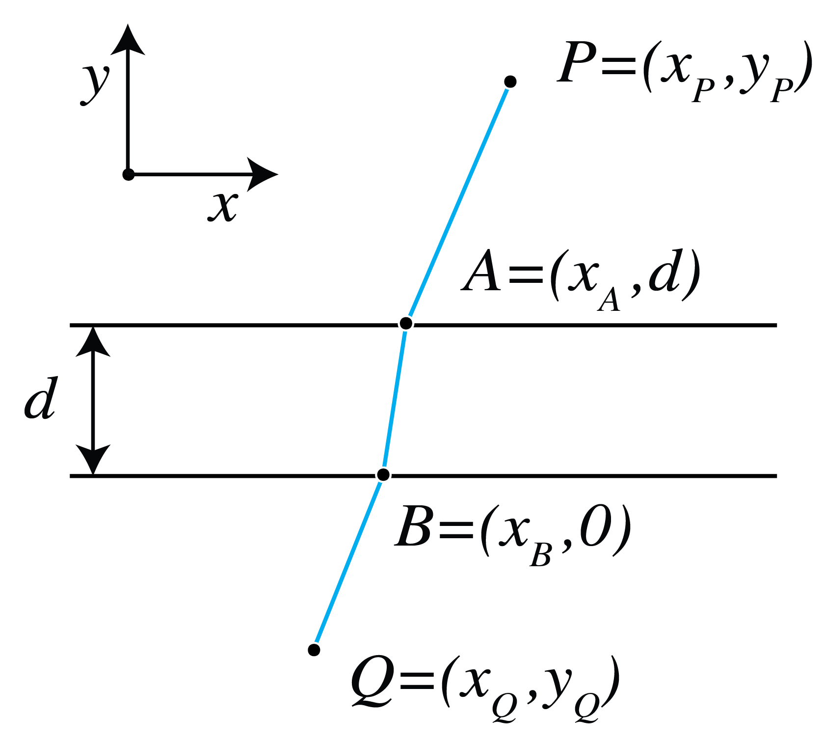
Figure 1:A ray through points and .
(a) Write a formula for the OPL of the ray from to as shown in Figure 1.
(b) Find the equations satisfied by and at a stationary OPL. Hint: set the partial derivatives of the OPL with respect to and equal to zero.
(c) Express the equations derived under b) in terms of , and and derive that Snell’s Law holds for the angles and :
Note that the relationship between and is independent of the refractive index and the thickness of the middle layer.
(d) Does Snell’s Law Eq. (1) hold irrespective of the number of layers and their thicknesses in between the two half spaces? Explain your answer.
(e) Derive Eq. (1) by using the boundary conditions for the tangential components of the electromagnetic field, using Maxwell’s boundary conditions for electromagnetic fields.
Problem 2.2 Perfect focusing by an ellipsoid and a hyperboloid.
Suppose that two media have indices and the source is far to the left in medium . We seek an interface that focuses the parallel incident rays at in medium , as in Figure 2. A plane perpendicular to the incident beam is a constant-phase reference plane.
(a) If point is on the interface sought, derive that
where the constant is the same for all points on the interface.
(b) Show that by moving the plane parallel to itself we can achieve that for the new plane
where . This is the focus–directrix definition of an ellipse in cross section, or an ellipsoid of revolution.
(c) Suppose next that . By the same phase-matching argument, show that the interface is a hyperboloid with as a focus.
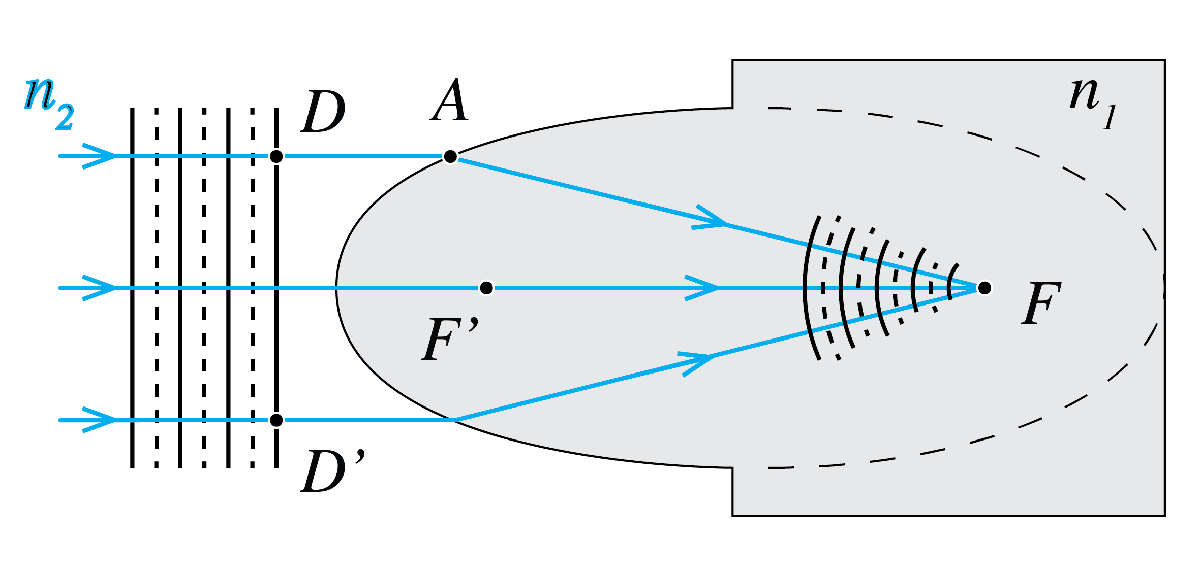
Figure 2:Ellipsoidal interface () focusing a parallel beam from medium at in medium . The hyperboloidal case is derived separately.
(d) Use the previous results to describe a lens with refractive index and having hyperboloid surfaces which perfectly image two given points S and P in the ambient medium with refractive index .
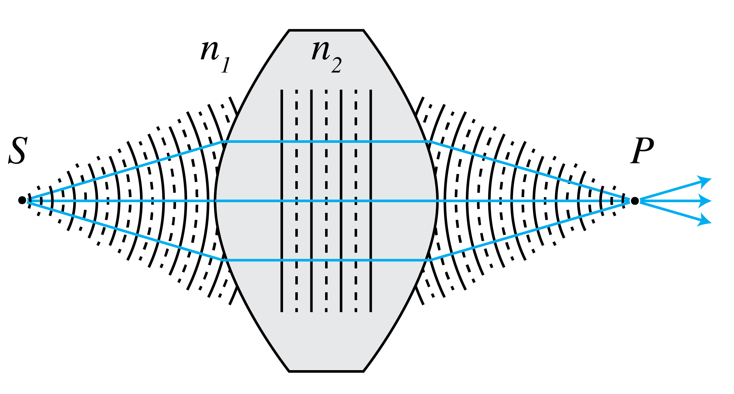
Figure 3:Lens with hyperboloid surfaces for perfect imaging of a pair of points.
Problem 2.3 Perfect focusing by a parabolic mirror
Next we consider perfect focusing of parallel rays in air () by a mirror. Let there be a parallel bundle of rays in air () and suppose we want to focus all rays at point .
(a) We draw a plane perpendicular to the rays as shown in Figure 4. The rays that hit have traversed the same optical path length. Draw a second surface parallel to . Consider rays hitting the mirror at and . Derive that
(b) Derive that
(c) Show that Eq. (4) is satisfied for points for which , and conclude that the mirror is a paraboloid with as focus and as directrix.
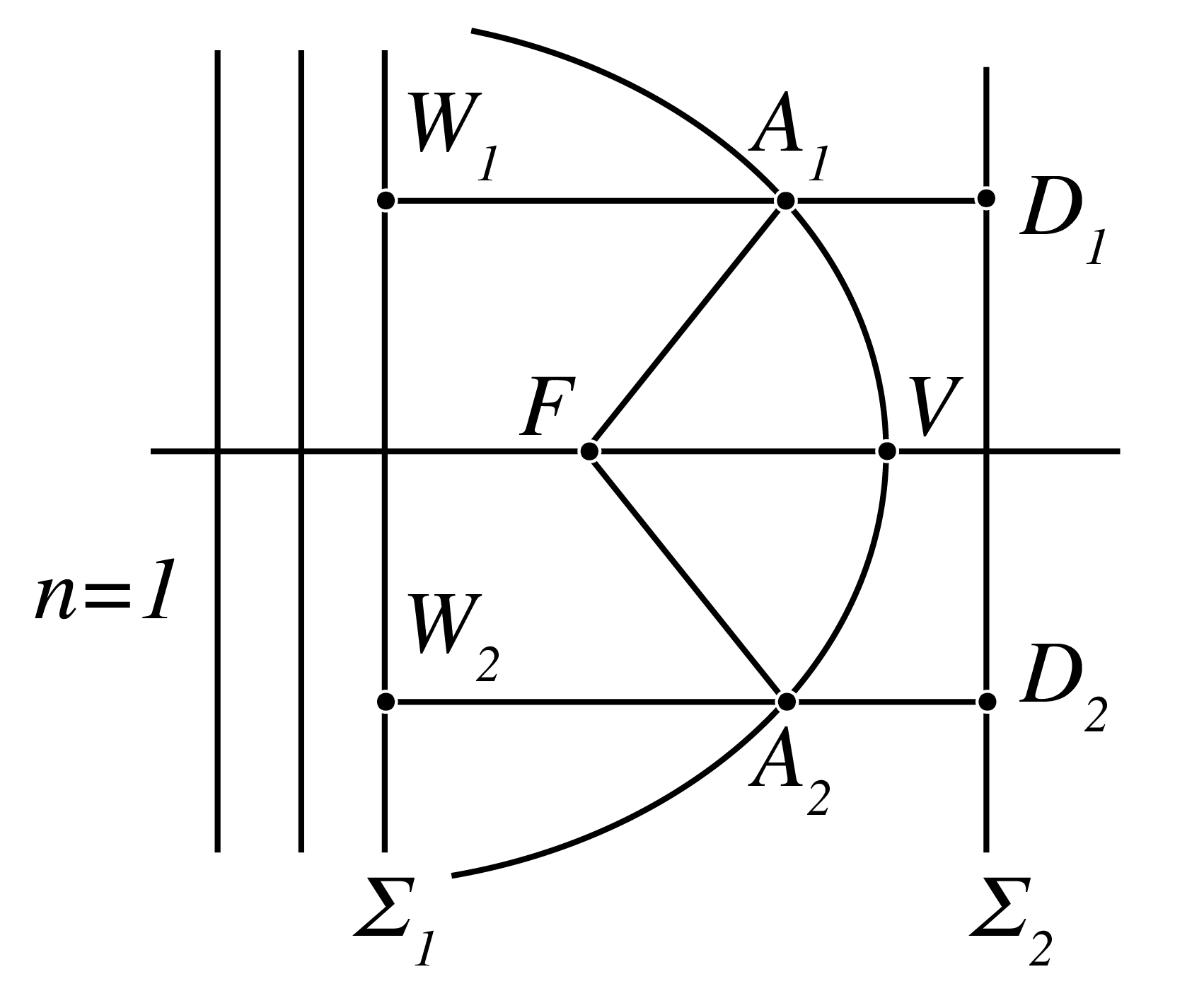
Figure 4:A paraboloid mirror.
Problem 2.4 Imaging of a virtual object.
A virtual object is at a distance behind a converging lens. The incoming rays would converge there if the lens were absent, as their dashed continuations in Figure 5 show. Construct the refracted rays for a lens of focal length .
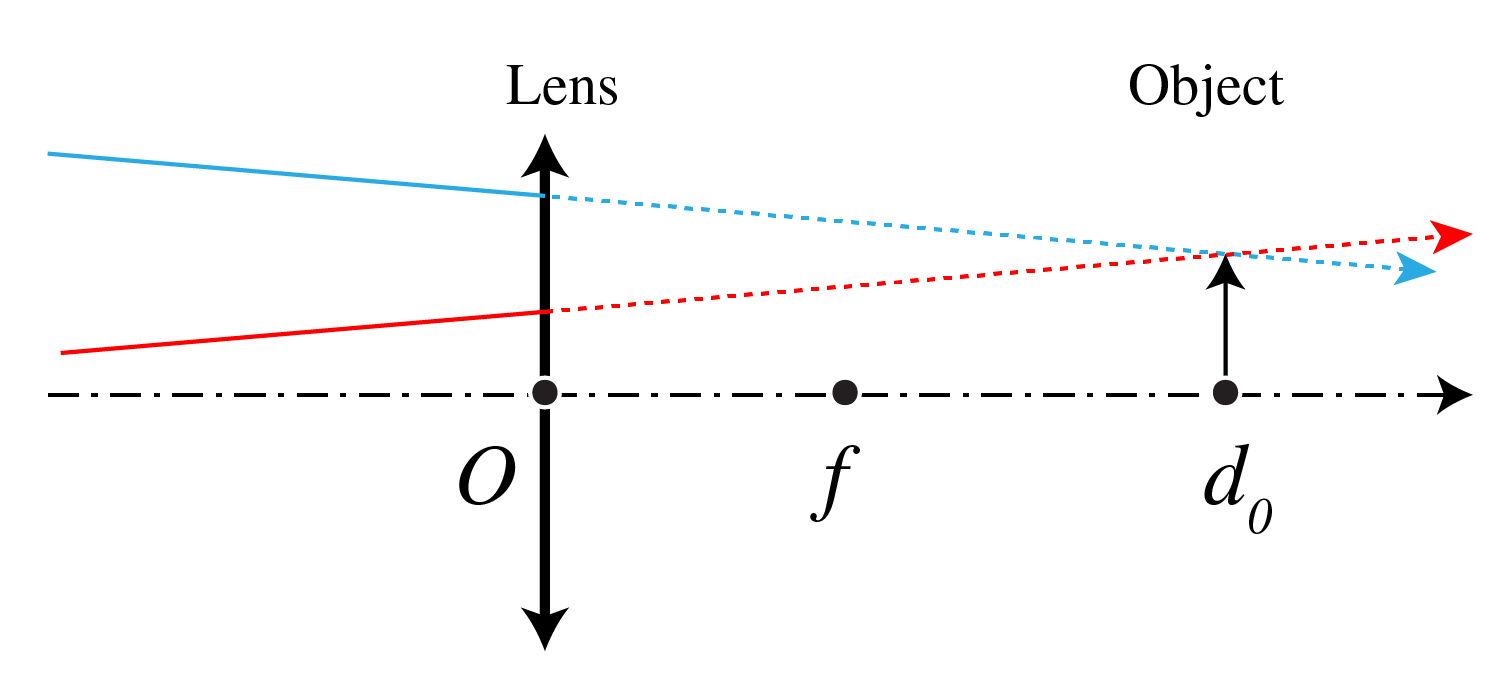
Figure 5:Converging incoming rays define a virtual object to the right of the lens; the dashed lines show their continuations before the lens’s refraction is constructed.
(a) Construct the image when cm, cm and the height of the object is 1 cm.
(b) Is the image real or virtual? Inverted or upright?
(c) Calculate the location of the image using the lens formula and compare it with your drawing. What is the magnification?
Problem 2.5 Suppose we have two thin lenses and . Lens is convergent (i.e. positive) with focal distance and lens is divergent (i.e. negative) with focal distance . The distance between the lenses is . Let there be an object at distance in front of lens , as shown in Figure 6.
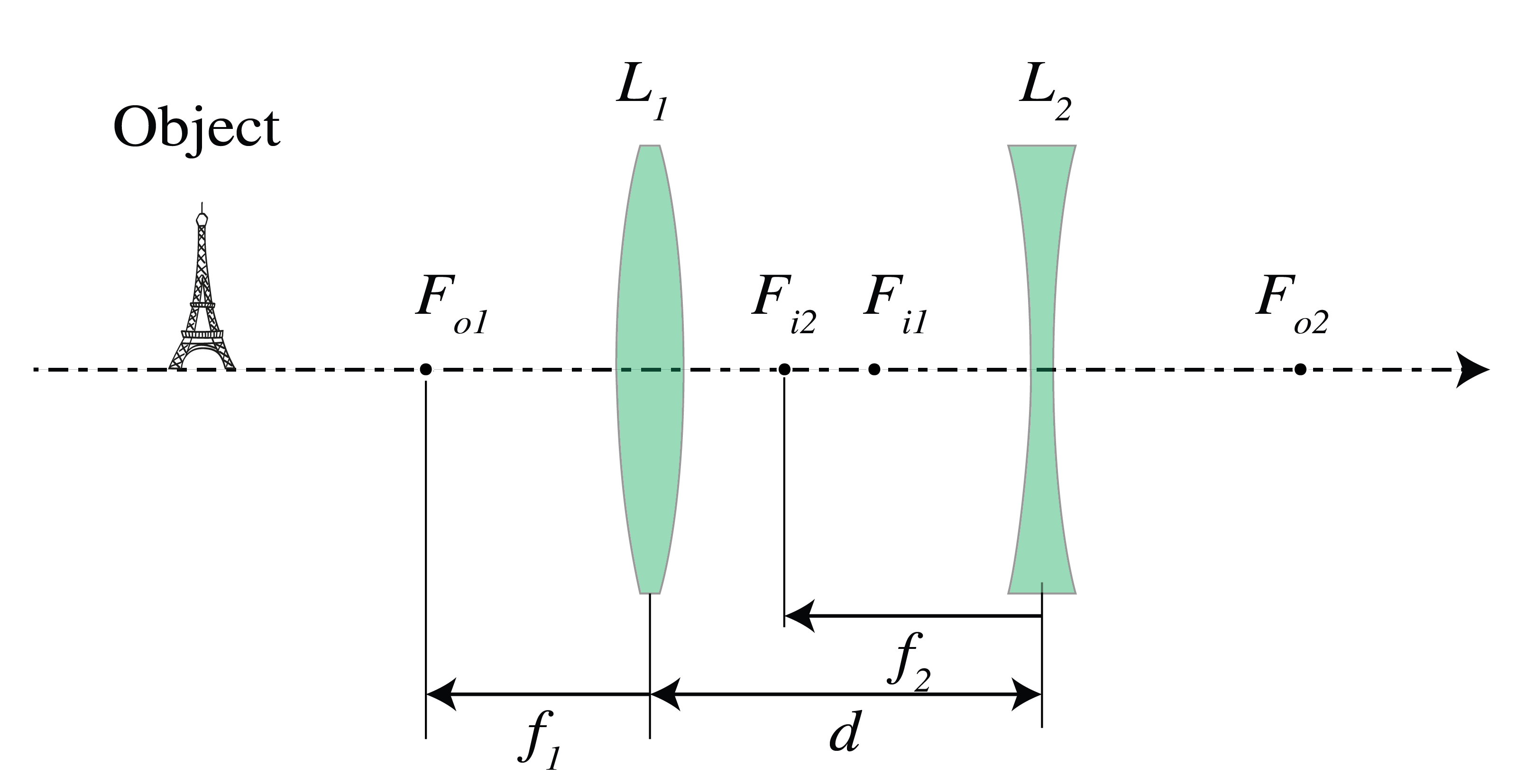
Figure 6:Converging lens followed by diverging lens at separation ; their object and image focal points are labeled.
(a) Derive the condition on the distance between the lenses such that the final image is real.
(b) Let and . What should be the distance such that the final image is real and the magnification is 2?
Problem 2.6 System matrix for imaging by a spherical surface.
Consider a spherical surface with radius of curvature , with a medium of refractive index () to the left (right) of the surface).
(a) Derive the ray matrix between a plane to the left of the surface at a distance from the vertex and a plane to the right of the surface at a distance from the vertex. (As always, the rays are assumed to propagate from left to right.)
(b) Derive the conditions such that the plane at distance is the image of the plane at distance . Express the formula in coordinates , with respect to the vertex as origin and show that the result is identical to formula Eq. (26)
(c) Assume that , and cm. Show by construction using the paraxial version of Snell’s Law that when the object is virtual with cm, the coordinate of the image point is given by cm, in agreement with the formula derived in b).
(d) Construct again the image when cm but now for the case that cm and verify that the coordinate of the image point agrees with the formula derived in b).
Problem 2.7 The purpose of this problem is to derive the Lensmaker’s formula for a thin lens by applying the imaging formula of a spherical surface twice. The image of a point as shown in Figure 7 is computed in two steps. First the intermediate image of by the spherical surface with vertex is computed and then this intermediate image is imaged by the spherical surface with vertex .
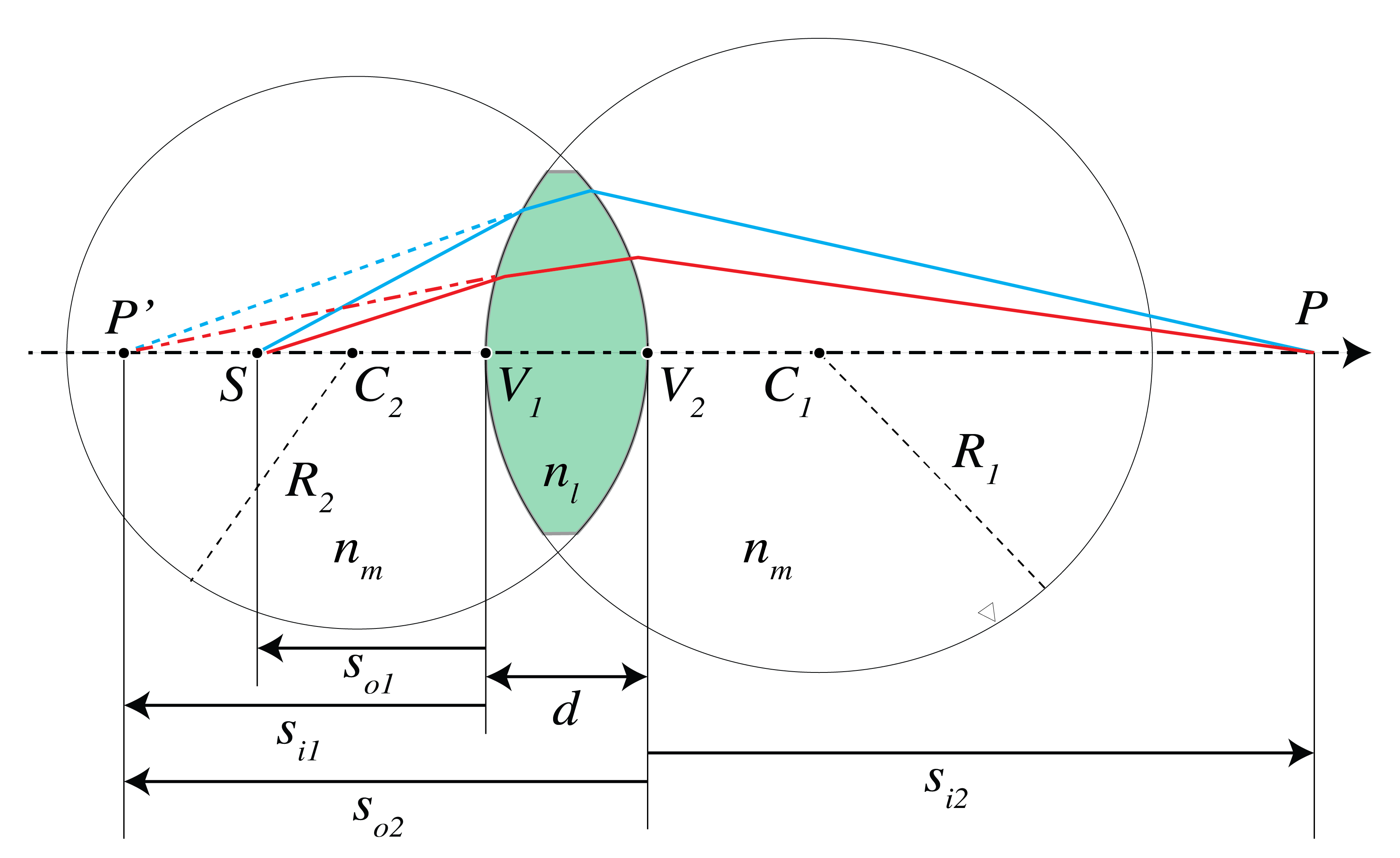
Figure 7:A spherical lens made of glass of index in a medium of index . The point is imaged in .
(a) Use Eq. (26) to deduce that when is imaged by the first spherical surface as if the second spherical surface were absent, the -coordinate of the image with respect to the origin at satisfies:
where is the -coordinate of with respect to the origin at .
(b) Show that with respect to the origin at the -coordinate of is
(c) Show that the -coordinate of P with respect to the origin at satisfies
(d) Add the results of a) and c) to derive
(e) Derive the Lensmaker’s formula for the thin lens (see the Ray Matrix chapter) by taking the limit in d).
Problem 2.8 System matrix for focusing.
Consider a ray transfer matrix
between two planes.
(a) Suppose that any ray that is parallel to the optical axis in the first plane goes through a point on the optical axis in the second plane. This means that the second plane is the image focal plane of the system. What does this imply for the elements of the transfer matrix?
(b) Suppose that the first plane is the object focal plane, so that any ray emitted by the point on the optical axis in the first plane becomes collimated in the second plane. What does this imply for the elements of the transfer matrix?
(c) Consider two thin lenses with distance and focal distances and . Derive the transfer matrix linking the plane immediately before the first lens with the plane immediately behind the second lens. You may assume that the lenses are in air with refractive index .
(d) Use the condition that you found in a) to derive the image focal distance of a system consisting of two thin lenses with image focal distances and and distance . Verify that the result agrees with the distance for the image focal plane Eq. (45). Hint: let be the distance of the image focal point of the two-lens system to the second lens. Write the transfer matrix between the plane immediately before the first lens and the plane through the image focal point.
(e) Add a third thin lens with image focal distance in contact with the second lens. Derive the ray matrix of this system.
(f) Let be the distance from the image focal plane to the third lens. Use the condition derived in a) and the ray matrix derived in e) to derive .
Problem 2.9 Matrix for two thin lenses.
(a) Consider two thin lenses in a medium of refractive index . Their powers are and , and the distance between them is . Use the ray vector , with angle first and height second. Derive that the matrix between the planes immediately to the left of the first lens and the plane immediately to the right of the second lens is given by
(b) Define the combined power . Show that the image focal coordinate measured from the second lens and the object focal coordinate measured from the first lens are:
(c) With , verify that these formulae agree with Eq. (46) and Eq. (45).
Problem 2.10 Entrance pupil of a system of two lenses. Consider a system of two lenses and with distance . The left lens has image focal distance and , are the radii of the lens apertures of and .
(a) Let lens be convergent with and let the distance be . Furthermore, let and . Determine by construction with a ruler the entrance pupil. Compute also its position and radius using the thin-lens imaging equation and derive the tangent of the angle that the marginal ray makes with the optical axis for an object on the optical axis at 4 cm to the left of .
(b) Same question when is a divergent lens with , and .
Problem 2.11 Diaphragm in a system of two thin lenses. Determine the entrance and exit pupils by ray construction, thin-lens imaging, and the matrix method. The situation is as shown in Figure 8. The focal distances of the two thin lenses are cm and cm and their distance cm. Suppose that the aperture stop is as shown in Figure 8. It is at a distance of cm in front of the lens and has a diameter cm.
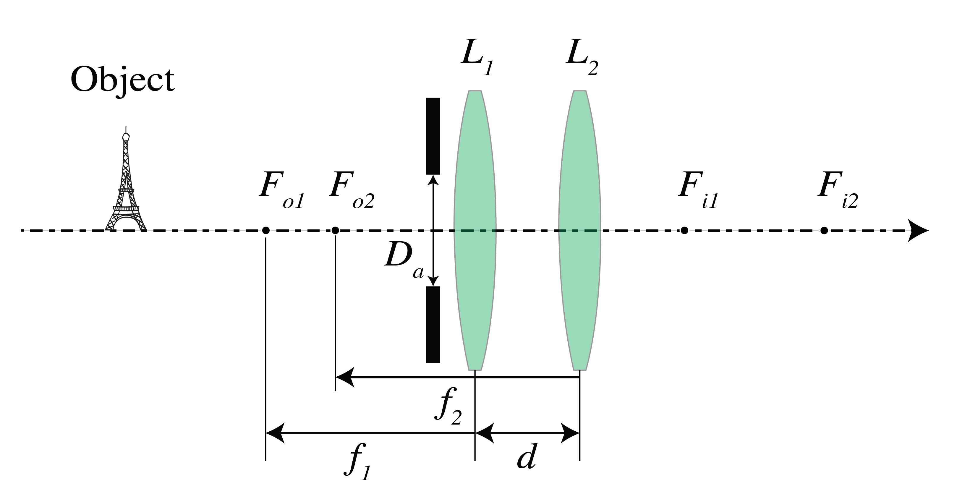
Figure 8:Optical system with two thin lenses and an aperture stop. Lens L₁ (focal length f₁ = 10 cm) and lens L₂ (focal length f₂ = 12 cm) are separated by distance d = 6 cm, with an aperture diaphragm (diameter Dₐ = 5 cm) positioned 1.5 cm in front of L₁. This configuration is used to analyze entrance and exit pupils.
(a) Determine the position of the entrance pupil and its diameter by the mentioned three methods.
(b) Determine the position of the exit pupil and its diameter by the mentioned three methods.
(c) Compute the -number of the system.