Problem 7.1 Consider a radiating time-harmonic point source in . The complex field at the observation point , where , is given by:
where is a given complex number whose modulus is proportional to the source strength.
(a) Derive that for fixed and sufficiently large such that the source-dependent phase is negligible, the field can be approximated by
(b) Let there be a second point source at , with complex source strength with . We assume that both point sources are coherent. This means that there is such that . Show that the field at for large due to the two point sources can be written as
where .
(c) For which small angles does the far-field intensity vanish? Show that the distance between the point sources can be determined from the angular separation of the zeros of the intensity. Does the angular separation depend on the phase difference ?
(d) What should be the phase difference between the point sources such that for on the screen at large distance the intensity vanishes?
Problem 7.2 Consider two slits of equal width in a non-transparent screen of thickness in the plane as shown in Figure 1. The screen is illuminated by a plane wave with unit amplitude and propagating in the positive -direction. In the second slit there is a piece of glass with refractive index and thickness . In the first slit there is vacuum. Neglect interface reflections, absorption, and the small lateral displacement inside the glass; treat it as an ideal phase-only insert.
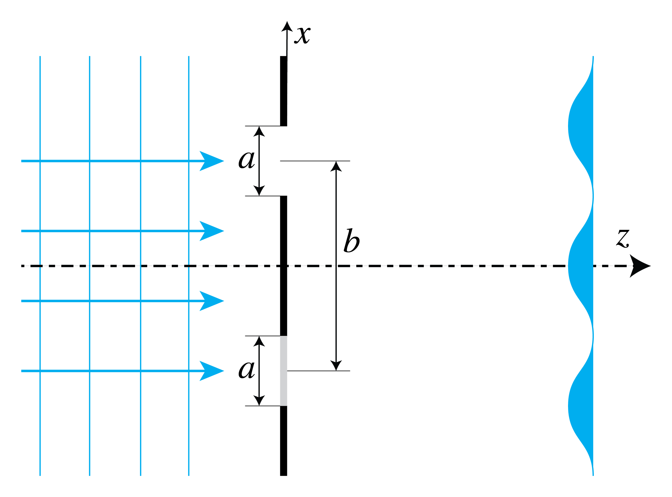
Figure 1:Two slits with centers separated along and long sides parallel to in a dark screen of thickness . The lower slit is filled with glass, the upper is in vacuum.
(a) If the field immediately behind slit 1 has complex amplitude equal to 1, explain that the field immediately behind slit 2 is given by
with , where is the vacuum wave number.
(b) Derive (using Eq. (2) or in another way) that the Fraunhofer intensity pattern on a screen along the line at large distance is given by (up to factors that do not depend on ).
In deriving this result you may omit all factors that are independent of and . If you use Eq. (3) you may take , .
(c) Make a sketch of this intensity pattern, showing the zeros and maxima as a function of when , and . Explain where the envelope and the other factor that depends on are caused by.
Problem 7.3 We consider the optical set-up shown at the left of Figure 2 where a point source at point is above a plane mirror in the plane . The time-harmonic field emitted by the point source without the mirror being present is in complex notation given by:
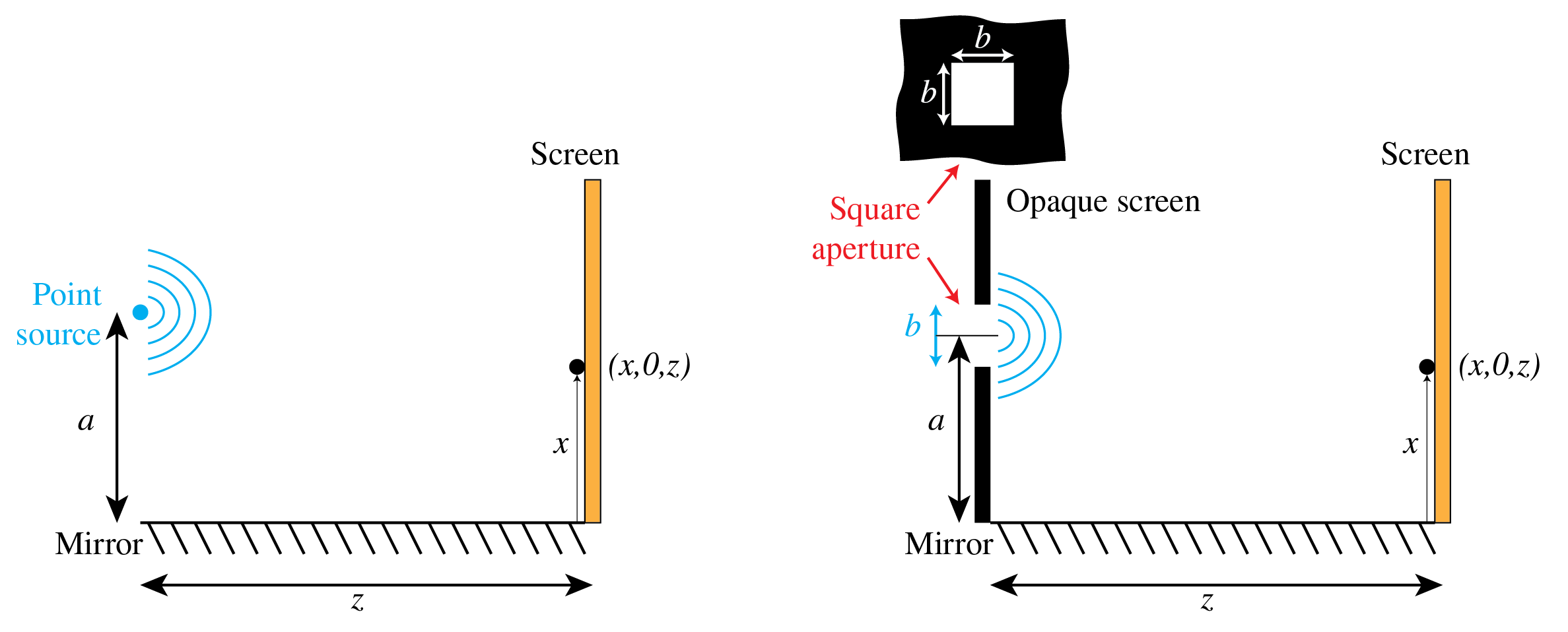
Figure 2:Lloyd mirror configuration with a point source (left) and a rectangular aperture in a dark screen (right), above a mirror and with a screen at distance where the field is observed.
(a) Let be the field reflected by the mirror. Assume that the mirror is perfect so that the total field is zero on the surface of the mirror, i.e. when . Show that the reflected field can be considered to be emitted by a point source in , which is the image of the original point source by the mirror, and which is out of phase with the original point source and has the same strength.
(b) Consider the field on a screen at . According to (a) the field in the presence of the mirror can be considered to be radiated by two point sources, namely at and , that are of equal strength and out of phase with each other. Assume that is so large that the spherical waves emitted by these point sources and arriving at the screen can both be considered to be plane waves. Derive that the point on the screen with smallest where the field is zero is given by
where is the wavelength. In your derivation use path length differences of interfering rays and make a drawing.
(c) What happens with this zero and with the fringe pattern on the screen when the perfect mirror is replaced by a dielectric such as a piece of glass?
(d) Suppose now that there is a second point source at above the mirror and suppose that it has the same strength and is in phase with the point source in . Assume again that the mirror is perfectly reflecting and derive (again by considering path length differences and using a drawing) that the smallest for which a zero occurs at point on the screen is given by
(e) Derive the smallest for which the field is zero at when the two point sources at and are mutually incoherent. Use again path length differences and make a drawing.
(f) Next suppose that there is a square aperture with center at and sides of length parallel to the - and -directions in an opaque (i.e. dark) screen above the mirror as shown at the right of Figure 2. The aperture is illuminated by a plane wave that propagates parallel to the -axis, hence the field in the aperture has constant phase and amplitude. Compute the smallest positive for which a zero occurs at on the screen at large distance . Use again path length differences and a drawing in your derivation.
Problem 7.4 Note: to answer the following questions it is NOT necessary to compute diffraction integrals.
(a) Consider two equally strong point sources which with respect to a coordinate system are at and , where the -axis is the optical axis. Suppose the point sources are mutually coherent, emit in phase, and have separation so that the first zero is within the paraxial range. The maximum intensity on a screen at large (i.e. Fraunhofer) distance is then on the optical axis. Show that the smallest angle with the optical axis at which there is a zero on this screen is given by .
(b) What is the smallest angle with the optical axis at which there is a zero on the screen when the two point sources emit with phase difference ?
(c) Are there any zeros on the screen when the two point sources are mutually incoherent?
(d) Consider now two identical apertures in an opaque screen at . One aperture has its center at and the other has its center at . The apertures are illuminated by a time-harmonic plane wave at perpendicular incidence to the screen (i.e. propagating parallel to the -axis). Show that the two-aperture interference factor vanishes at , whatever their identical shape. Could zeros of the single-aperture envelope occur at smaller angles?
(e) Suppose that the plane wave is incident at some angle different from . Let its complex field be given by
where . Suppose that (modulo ). Find the signed angle of the interference zero closest to the optical axis, assuming the single-aperture envelope does not vanish first. Explain how the oblique illumination shifts the pattern.
(f) Now imagine that both (identical) apertures are filled with glass plates with thickness that varies with position. The two glass plates are identical and they are identically positioned in each of the two apertures. Imagine that we illuminate the apertures with a plane wave at perpendicular incidence. The field transmitted by each aperture is now a rather complicated function of position, however the transmitted fields behind both apertures are identical. Does the two-aperture interference zero remain at , or do the identical glass plates shift it? What can change about the envelope? Explain your answer.
Problem 7.5 Bessel beams.
Suppose there is a mask in the entrance pupil of radius of a positive thin lens with image focal length with a thin ring-shaped aperture at with width . If a plane wave with amplitude is at perpendicular incidence on the mask, the field immediately behind the mask is given by
(a) Use the integral
to derive that for sufficiently small , the field in the focal plane, apart from the common lens-propagation prefactor and quadratic phase, is approximately
(b) The beam obtained this way is called a Bessel beam. Explain why this beam has a very long focal depth.
(c) In the thin-ring approximation , suppose that a full circular pupil illuminated with unit amplitude and the ring pupil carry the same incident power. Show that then the amplitude of the Bessel beam is given by
(d) Derive that the ratio of the field amplitudes in the focal point of the Bessel beam: and the Airy spot: is given by
If and this becomes
The finite ring in the plotted example gives about 0.44 when its exact area is used; the displayed formula uses the thin-ring approximation. This is the case shown in Figure 3.
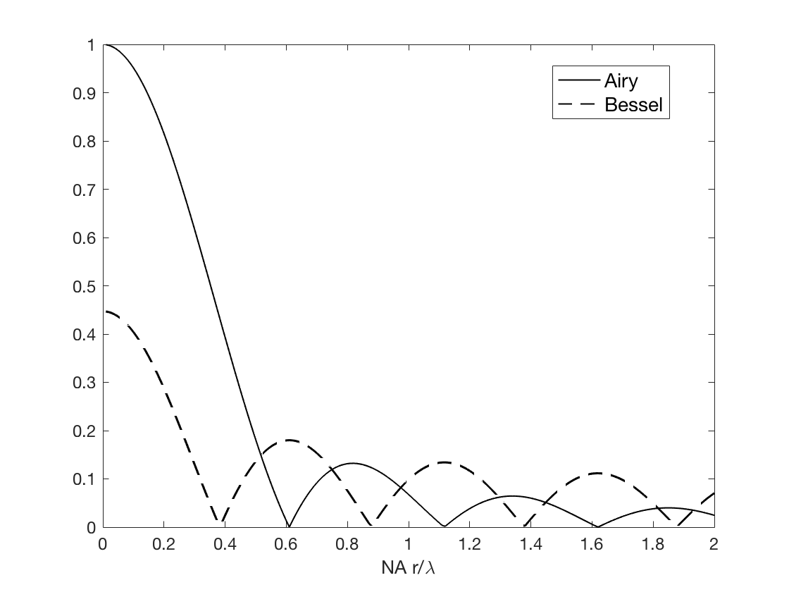
Figure 3:Amplitude in the focal plane of a Bessel beam and of an Airy spot with the same total energy. The lens pupil has radius , the ring aperture of the Bessel beam case is at the outer edge of the pupil () and has width and the .
(e) The Bessel beam has stronger side lobes than the Airy spot. Explain the reason.
Problem 7.6 Stellar interferometry.
Observe a star through a narrow spectral band centered at vacuum wavelength . Model it as a distant spatially incoherent source with angular brightness , where specifies the transverse propagation direction of light arriving at Earth. Assume paraxial propagation, negligible temporal decorrelation across the instrument paths, and equal collection efficiencies. Let two collectors have transverse positions and and baseline .
(a) Show that one source element at direction contributes a plane-wave factor at collector position , apart from a common phase.
(b) Use the independence of different source elements to derive the mutual coherence
State the normalized complex visibility .
(c) If the two collected beams have equal mean intensity, how is the measured fringe contrast related to ? What additional phase information is needed to reconstruct an image from measurements at many baselines?
(d) Estimate the angular scale probed by a largest baseline . Explain why limited baseline coverage and measurement noise also affect the reconstructed image.