Rotational motion exists everywhere in the universe. The motion of electrons about an atom and the motion of the moon about the earth are examples of rotational motion. Objects cannot be treated as particles when exhibiting rotational motion since different parts of the object move with different velocities and accelerations. Therefore, it is necessary to treat the object as a system of particles.
When all parts of a rigid body move parallel to a fixed plane, then the motion of the object is referred to as plane motion. There are two types of plane motion, which are given as follows:
The pure rotational motion: The rigid body in such a motion rotates about a fixed axis that is perpendicular to a fixed plane. In other words, the axis is fixed and does not move or change its direction relative to an inertial frame of reference.
The general plane motion: The motion here can be considered as a combination of pure translational motion parallel to a fixed plane in addition to a pure rotational motion about an axis that is perpendicular to that plane. This chapter discusses the kinematics and dynamics of pure rotational motion.
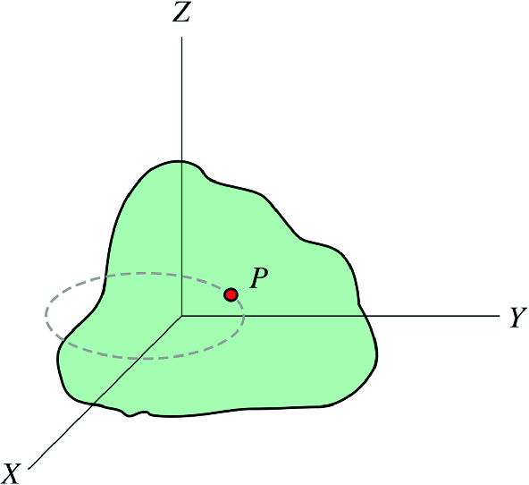
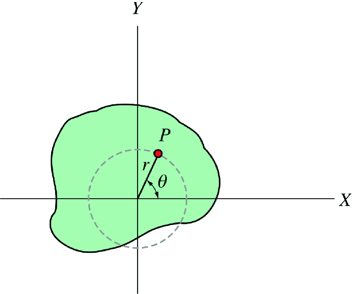
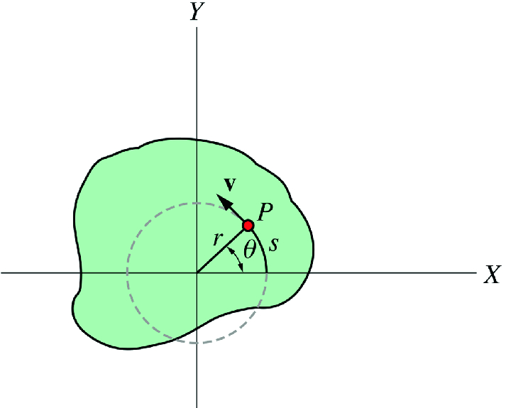
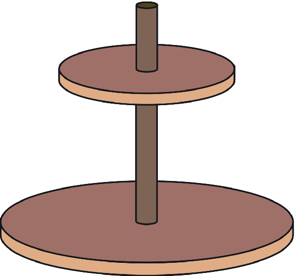
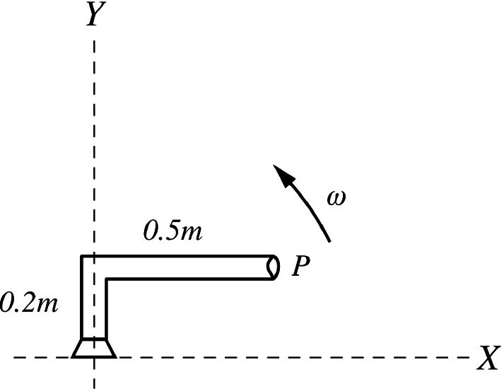
Suppose a rigid body of an arbitrary shape is in pure rotational motion about the z-axis (see Fig. Figure 1). Let us analyze the motion of a particle that lies in a slice of the body in the x-y plane as in Fig. Figure 2. This particle (at point P) will rotate in a circle of fixed radius r which represents the perpendicular distance from P to the axis of rotation. If you look at any other particle in the object you will see that every particle will rotate in its own circle that has the axis of rotation at its center. In other words, different particles move in different circles but the center of all of these circles lies on the rotational axis. Suppose the particle moves through an arc length s starting at the positive x-axis. Its angular position is then given by
r and θ are the polar coordinates of a point in a plane (which was mentioned in Sect. 2.6) where θ is always measured from the positive x-axis. Because θ is the ratio of the arc length to the radius, it is a pure (dimensionless) number. The unit usually used to measure θ is the radians (rad). One radian is defined as the angle subtended by an arc of length that is equal to the radius of the circle. Since one rotation (360∘) corresponds to θ=2πr/r=2π rad, it follows that:
Note that if the particle completes one revolution, θ will not become zero again, it is then equal to 2πrad. Thus for example for three revolutions the angular position is given by
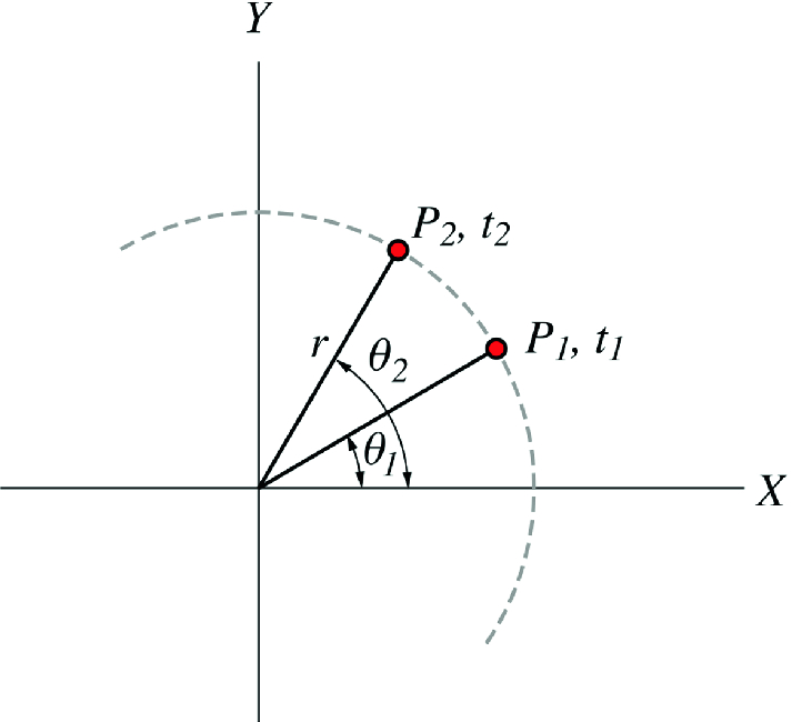
Suppose that the particle in Fig. Figure 2 is at point P1 at t1 and at point P2 at t2 where it changes its angular position from θ1 to θ2 (see Fig. Figure 3). Its angular displacement is then given by
△θ is positive for counterclockwise rotations (increasing θ) and negative for clockwise rotations (decreasing θ). If the particle undergoes this angular displacement during a time interval △t, the average angular velocity ω is then defined as
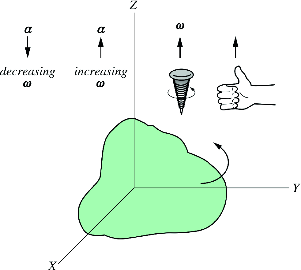
where α is in rad/s2 or s−2. Note that ω is positive for increasing θ and negative for decreasing θ, while α is positive for increasing ω and negative for decreasing ω. When a rigid body is in pure rotational motion, all particles in the body rotate through the same angle during the same time interval. Thus, all particles have the same angular velocity and the same angular acceleration. Therefore, ω and α describes the motion of the whole body In the case of pure rotational motion, the direction of ω is along the axis of rotation (also see Sect. 7.4 Vector Relationship Between Angular and Linear Variables), it can be determined by the right-hand rule or of advance of a right-handed screw as in Fig. Figure 4. The direction of α is in the same direction of ω if ω is increasing or in the opposite direction if ω is decreasing.
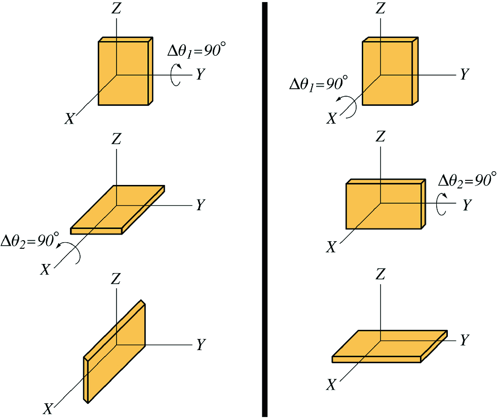
The quantities θ,ω and α in pure rotational motion are the rotational analog of x, v and a in translational one-dimensional motion. The vectors ω and α are not used in the case of pure rotational motion, they are used in the general rotational motion when the axis of rotation changes its direction with time. Note that only the infinitesimal angular displacement dθ can be represented by a vector but not the finite angular displacement △θ. This is because the finite angular displacement △θ does not obey the commutative law of vector addition (see Fig. Figure 5) and therefore cannot be represented by a vector. Hence, the instantaneous angular velocity and acceleration (ω and α) can be represented by vectors but not their average values (ω and α).
Figure 4:The direction of ω is along the axis of rotation and can be determined by the right-hand rule or of advance of a right-handed screw
Figure 5:Changing the order of addition will change the final result
A pure rotational motion with constant angular acceleration is the rotational analogue of the pure translational motion with constant acceleration. The corresponding kinematic equations of pure rotational motion can be obtained by using the same method that is used for obtaining the kinematic equations of pure translational motion. To show this, consider a rigid object rotating with a constant angular acceleration during a time interval from t1 to t2 through an angle from θ1 to θ2. Let t1=0,t2=t,ω1=ωo,ω2=ω,θ1=θo, and θ2=θ. Because the angular acceleration is constant it follows that the angular velocity changes linearly with time and the average angular velocity is given by
Note that as mentioned earlier, if a rigid object is in pure rotational motion, all particles in the object have the same angular velocity and angular acceleration. Different particles move in different circles but the center of these circles lies at the axis of rotation. As the rigid body rotates, a particle in the body will move through a distance s along its circular path (see Fig. Figure 6). The angular displacement of the particle is related to s by
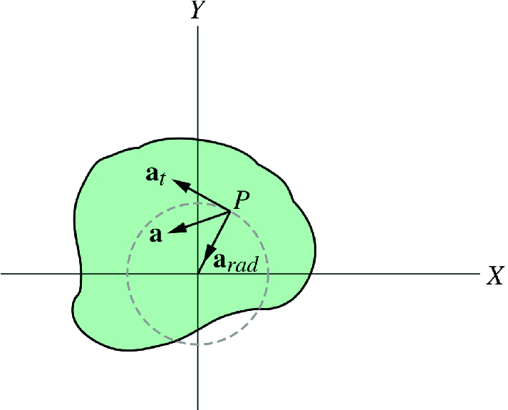
Therefore, the farther the particle is from the rotational axis the greater its linear speed. The direction of the linear speed of the particles is always tangent to the path (as mentioned in Sect. 2.2.3). In Sect. 2.4.6 we have seen that a particle in nonuniform circular motion has both tangential and radial components of acceleration. The radial component is due to the change in the direction of the velocity and is given by
7.4 Vector Relationship Between Angular and Linear Variables
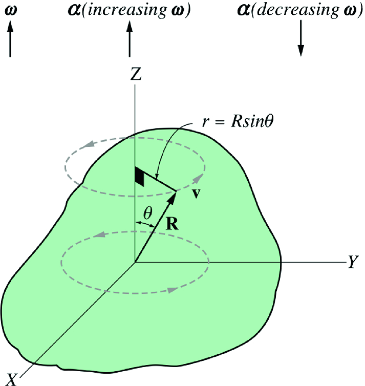
Consider a rigid body in pure rotational motion about a fixed axis (for example the z-axis). For any particle in the object, its linear velocity is given by
where R is the position vector of the particle from the origin (see Fig. Figure 9) and θ is the angle between the position vector and the z-axis. As shown in Fig. Figure 9, the direction of y is perpendicular to the plane formed by ω and R where it can be verified using the right-hand rule. Therefore, by using the definition of vector product we may write
Furthermore, the direction of α×R is tangent to the circular path of the particle at any instant (see Fig. Figure 9). Thus the quantity α×R is just the tangential component of the total acceleration
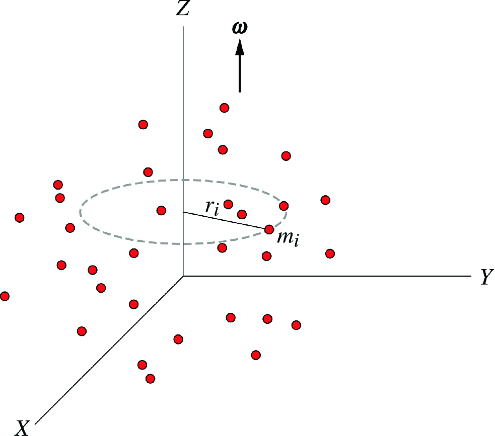
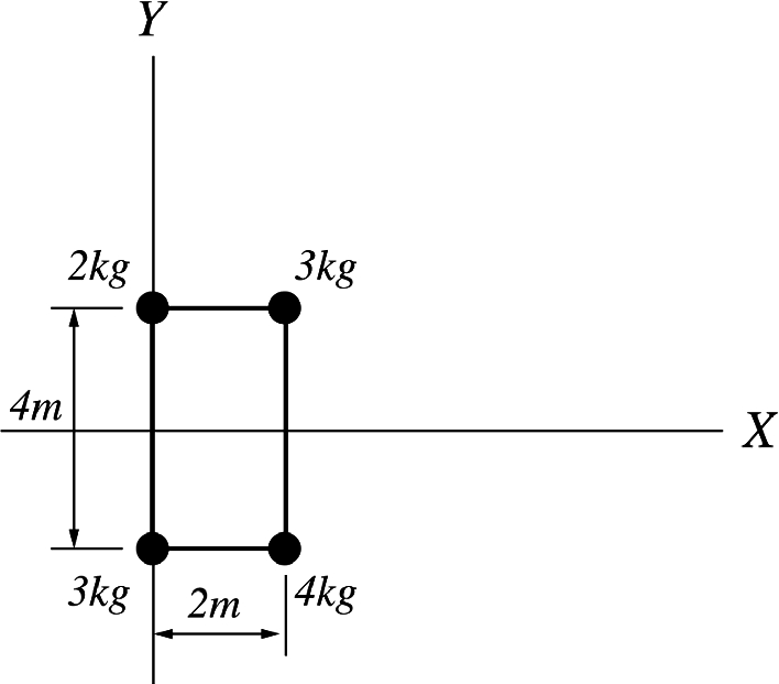
In Chap. 6 we have seen that the kinetic energy of a discrete system of particles is K=21i∑mivi2 where mi and vi are the mass and linear velocity of the ith particle respectively (see Fig. Figure 10). From Eq. 7.5, we have
This quantity shows how the mass of the system is distributed about the axis of rotation. Thus, to find the rotational inertia, the axis of rotation must be specified. If the rotational axis changes its position or direction, I changes as well. The SI unit of the moment of inertia is kg m2. The rotational kinetic energy can thus be written as
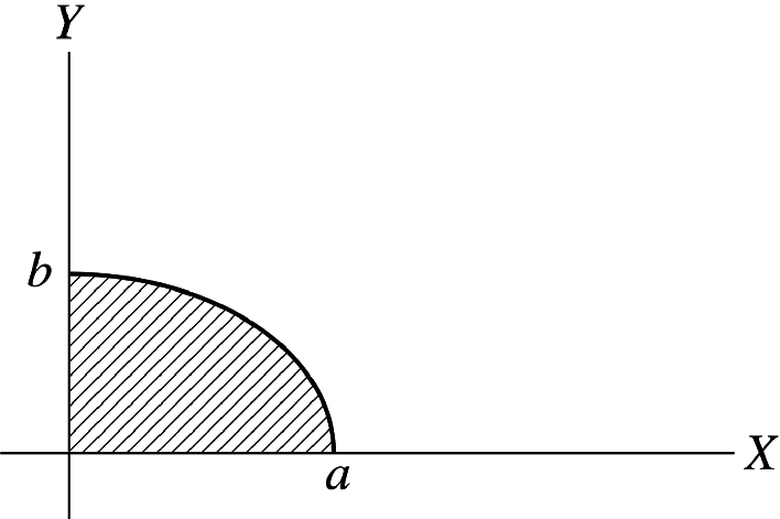
This quantity is the rotational analogue of the kinetic energy in translational motion. Note that this energy is not a new kind of energy; it is just the sum of the translational kinetic energies of the particles. For a rigid body which is a continuous system of particles, the sum is replaced by an integral
The parallel-axis theorem states that the moment of inertia I of a system about any axis that is parallel to an axis passing through the center of mass is
where Icm is the moment of inertia about an axis passing through the center of mass, M is the total mass of the system, and D is the perpendicular distance between the two parallel axes.
Proof
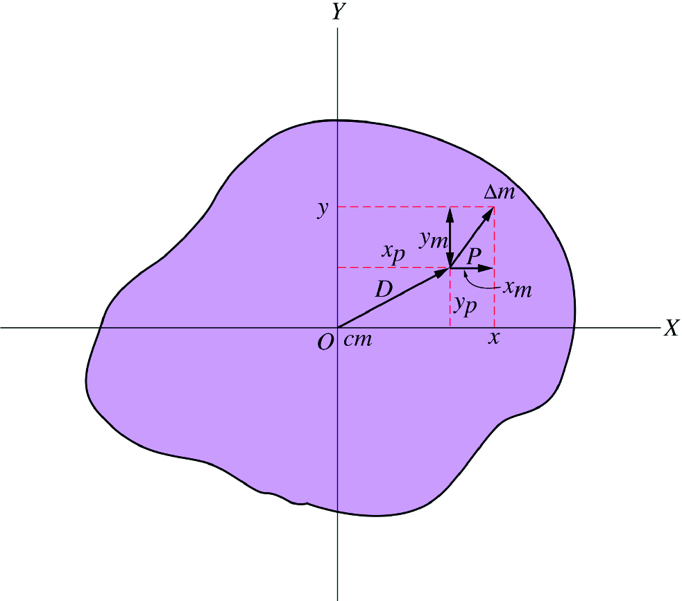
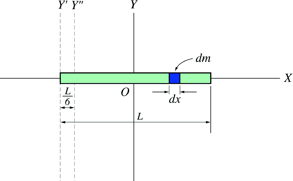
Consider an axis that is perpendicular to the page and passing through the center of mass of the object. Figure Figure 11 shows a thin slice of the object that lies in the x-y plane. Because the origin is taken at the center of mass we have
where x and y are the coordinates of the mass element dm from the center of mass (the origin). Now consider another axis that is parallel to the first axis and that passes through a point P as shown in Fig. Figure 11. Suppose that the x and y coordinates of P from the center of mass are xp and yp. The moment of inertia about an axis passing through P is
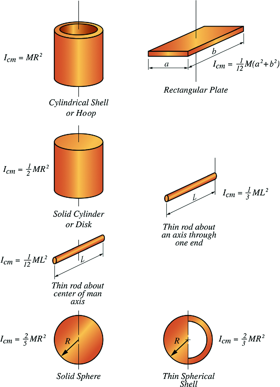
Special Moment of Inertia Fig. Figure 12 gives the rotational inertia of various rigid bodies of uniform density.
Figure 12:The rotational inertia of various rigid bodies of uniform density
7.7 Angular Momentum of a Rigid Body Rotating about a Fixed Axis
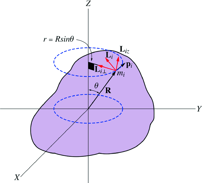
Consider a rigid body rotating about a fixed axis (the z-axis) with an angular speed ω as shown in Fig. Figure 13. The angular momentum of the ith particle with respect to the origin is given by
Figure 13:A rigid body rotating about a fixed axis (the z-axis) with an angular speed ω
Since the angle between Ri and pi is 90, then Li=Ripi. As seen from Fig. Figure 13, Li is not parallel to ω. Li can be analyzed to two components, a component parallel to ω written (Liz) and a component perpendicular to ω, (Li⊥). The magnitude of Liz is given by
where ri is the radius of the circle in which the particle is moving along and Ri=risinθ. Therefore, the total angular momentum of the rigid body along the z-direction is
where I is the moment of inertia of the rigid body about the rotational axis (z-axis). This equation can also be written in component form since Lz is parallel to ω, that is,
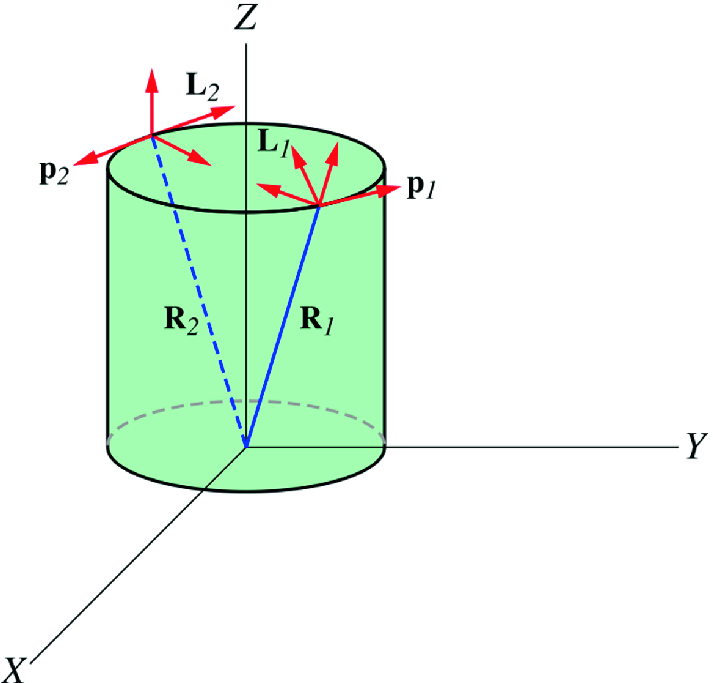
Therefore, if a rigid body is rotating about a fixed axis (say the z-axis), the component of the angular momentum along that axis is given by Eq. 7.10. Now suppose that the rigid body is symmetric and homogeneous and that it is rotating about its symmetrical axis (see Fig. Figure 14). For any two particles (1 and 2) opposing each other with an equal angular momenta L1 and L2, the perpendicular components, L1⊥ and L2⊥, of the angular momenta cancel each other out since they are in opposite directions. That leaves the parallel components L1z and L2z which add up since they have the same direction. For all particles in the object the total angular momentum is, therefore, given by
Note that Eq. 7.10 is valid for any rigid object in pure rotation where it only gives the component of the angular momentum that is parallel to the rotational axis. On the other hand, Eq. 7.11 is valid only for a symmetrical homogeneous rigid object rotating about its symmetrical axis, where the angular momentum in the equation is the total angular momentum and it is directed along the axis of rotation. The net external torque acing on the rigid object is equal to the rate of change of the total angular momentum of the object, i.e.,
In the case of any rigid object symmetrical or not, the net external torque acting on the object about the axis of rotation (say the z-axis) is equal to the rate of change of the component of angular momentum that is along that axis
Figure 16:A uniform thin rod of mass M and length L
Figure 17:A uniform thin plate of mass M and surface density σ
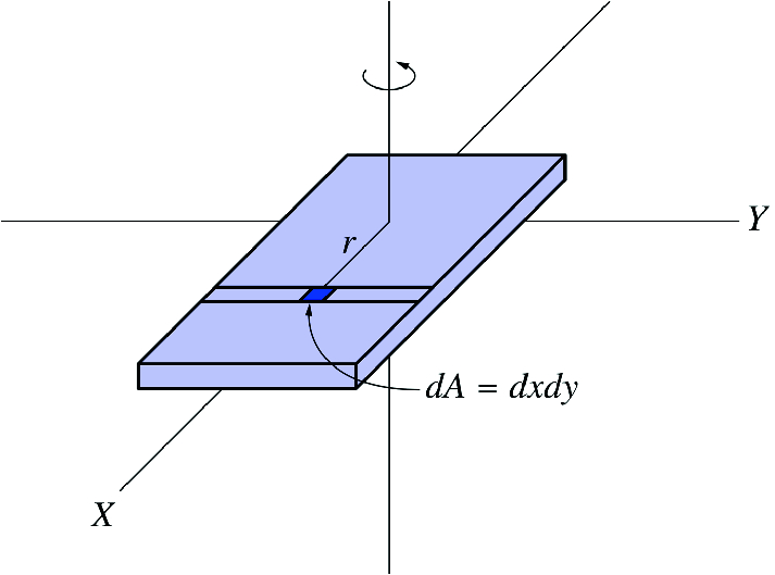
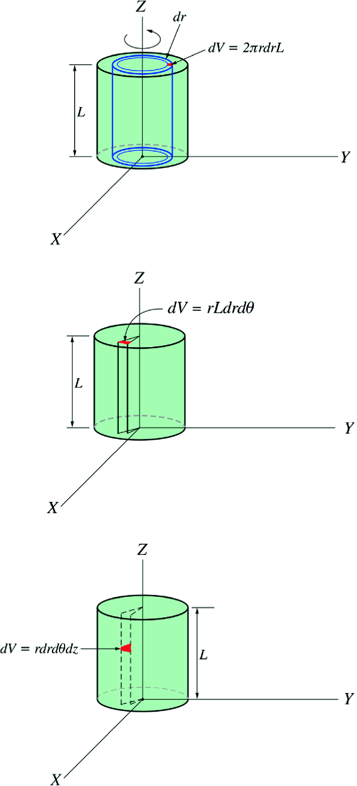
Figure 18:Calculating the moment of inertia of a uniform solid cylinder with the volume element defined in different ways
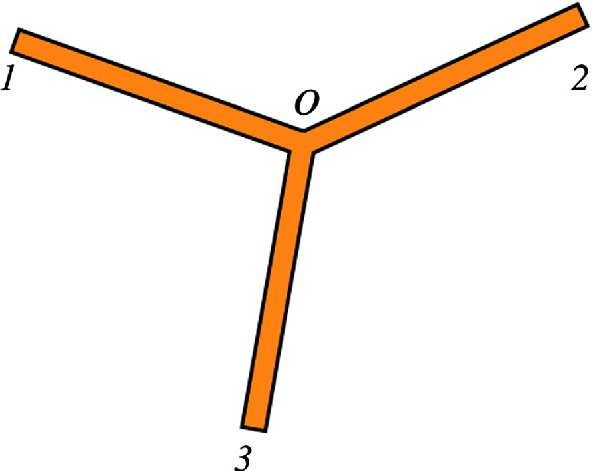
Figure 19:Three rods of length L and mass M are connected together
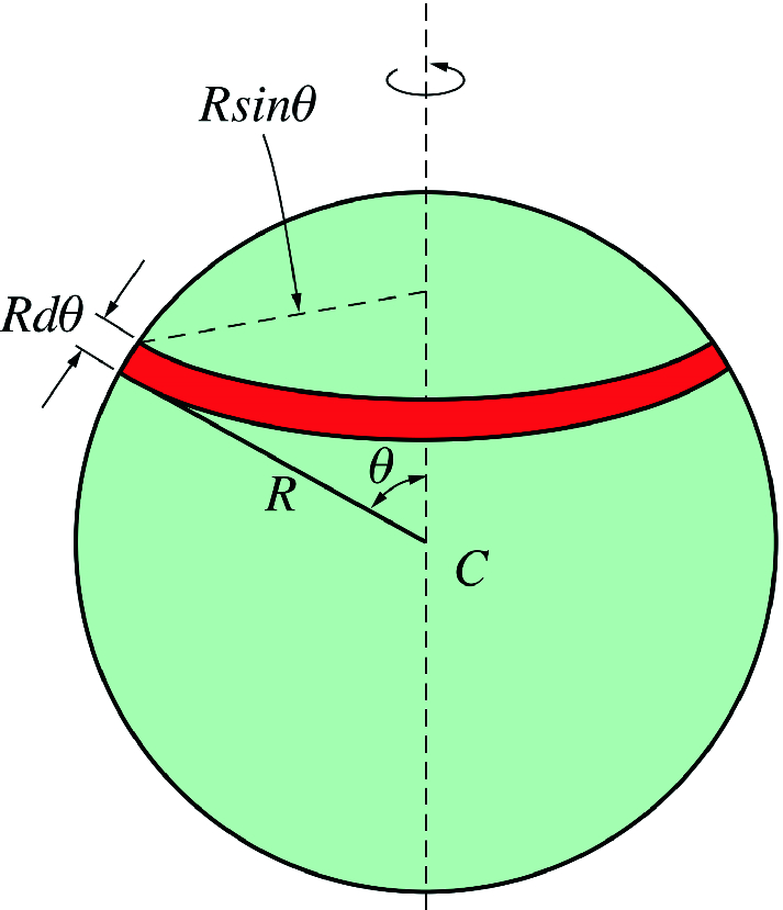
Figure 20:A spherical shell divided into thin rings
7.8 Conservation of Angular Momentum of a Rigid Body Rotating About a Fixed Axis
In Chap. 5 we have seen that if the net external torque acting on a system of particles relative to an origin is zero then the total angular momentum of the system about that origin is conserved
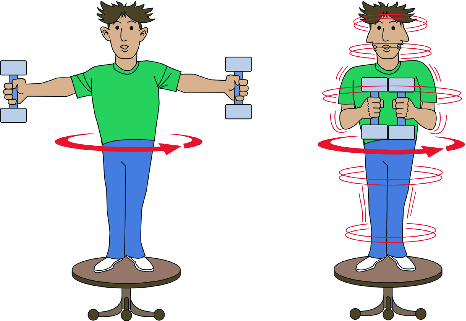
In the case of a rigid object in pure rotational motion, if the component of the net external torque about the rotational axis (say the z-axis) is zero then the component of angular momentum along that axis is conserved, i.e., if
That is, the angular momentum is not necessarily conserved in all directions. It is conserved in the direction where the net external torque is equal to zero.
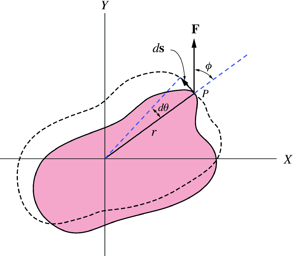
Consider a rigid body rotating about a fixed axis as in Fig. Figure 21. If a force that lies in the x-y plane is applied to the body at P, then the work done on the body if it rotates through an angle dθ is
Figure 21:A rigid body rotating about a fixed axis
The Work–Energy Theorem The work–energy theorem states that the work done by an external force while a rigid object rotate from θ1 to θ2 is equal to the change in the rotational energy of the object. This follows from Eq. 7.12 and by using the fact that along the axis of rotation the torque is given by τz=Iα (see Sect. 7.7 Angular Momentum of a Rigid Body Rotating about a Fixed Axis), thus
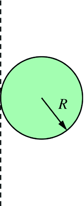
Figure 27:A uniform solid sphere rotating about an axis tangent to the sphere
Figure 28:A man stands on a platform that is free to rotate without friction about a vertical axis
Figure 29:A uniform disc rotating without friction. Another disc that is initially at rest is dropped on the first, the two will eventually rotate with the same angular speed due to friction between them