By the end of this section, you will be able to:
- Determine the angular frequency of oscillation for a resistor, inductor, capacitor series circuit
- Relate the circuit to a damped spring oscillation
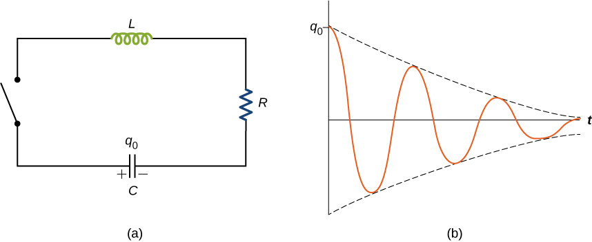
When the switch is closed in the RLC circuit of Figure 14.17(a), the capacitor begins to discharge and electromagnetic energy is dissipated by the resistor at a rate . With U given by Equation 14.37, we have
where i and q are time-dependent functions. This reduces to
This equation is analogous to
which is the equation of motion for a damped mass-spring system (you first encountered this equation in Oscillations). As we saw in that chapter, it can be shown that the solution to this differential equation takes three forms, depending on whether the angular frequency of the undamped spring is greater than, equal to, or less than b/2m. Therefore, the result can be underdamped , critically damped , or overdamped . By analogy, the solution q(t) to the RLC differential equation has the same feature. Here we look only at the case of under-damping. By replacing m by L, b by R, k by 1/C, and x by q in Equation 14.44, and assuming , we obtain
where the angular frequency of the oscillations is given by
This underdamped solution is shown in Figure 14.17(b). Notice that the amplitude of the oscillations decreases as energy is dissipated in the resistor. Equation 14.45 can be confirmed experimentally by measuring the voltage across the capacitor as a function of time. This voltage, multiplied by the capacitance of the capacitor, then gives q(t).
In the interactive circuit construction kit simulation, you can add inductors and capacitors to work with any combination of R, L, and C circuits with both dc and ac sources. Then you can measure and evaluate current and voltage, and graph them as a function of time.
With the interactive DC circuit construction kit simulation below, you can add inductors and capacitors to work with any combination of R, L, and C circuits with both dc and ac sources. Then you can measure and evaluate current and voltage, and graph them as a function of time.
In an RLC circuit, (a) Is the circuit underdamped, critically damped, or overdamped? (b) If the circuit starts oscillating with a charge of on the capacitor, how much energy has been dissipated in the resistor by the time the oscillations cease?
a. overdamped; b. 0.75 J
Summary
- The underdamped solution for the capacitor charge in an RLC circuit is
- The angular frequency given in the underdamped solution for the RLC circuit is
Key Equations
| Mutual inductance by flux | |
| Mutual inductance in circuits | |
| Self-inductance in terms of magnetic flux | |
| Self-inductance in terms of emf | |
| Self-inductance of a solenoid | |
| Self-inductance of a toroid | |
| Energy stored in an inductor | |
| Current as a function of time for a RL circuit | |
| Time constant for a RL circuit | |
| Charge oscillation in LC circuits | |
| Angular frequency in LC circuits | |
| Current oscillations in LC circuits | |
| Charge as a function of time in RLC circuit | |
| Angular frequency in RLC circuit |
The table has two columns and thirteen rows. The first column has the names of the equations and the second column lists the equation. From left to right, the first row contains “Mutual inductance by flux” and “M equals N subscript 2 phi subscript 21 divided by I subscript 1 equals N subscript 1 phi subscript 12 divided by I subscript 2”. The second row contains “Mutual inductance in circuits” and “epsilon subscript 1 equals minus M differential of I subscript 2 with respect to t”. The third row contains “Self-inductance in terms of magnetic flux” and “N phi subscript m equals L I”. The fourth row contains “Self-inductance in terms of emf” and “epsilon equals minus L differential of I with respect to t”. The fifth row contains “Self-inductance of a solenoid” and “L subscript solenoid equals mu subscript 0 N square A divided by l”. The sixth row contains “Self-inductance of a toroid” and “L subscript toroid equals mu subscript 0 N square h divided by 2 pi multiplied by natural log of R subscript 2 divided by R subscript 1”. The seventh row contains “Energy stored in an inductor” and “U equals half L I square”. The eighth row contains “Current as a function of time for a RL circuit” and “I opening parenthesis t closing parenthesis equals epsilon divided by R multiplied by opening parenthesis 1 minus exponential e power minus t divided by tau subscript L closing parenthesis”. The ninth row contains “Time constant for a RL circuit” and “tau subscript L equals L divided by R”. The tenth row contains “Charge oscillation in LC circuits” and “q opening parenthesis t closing parenthesis equals q subscript 0 cosine opening parenthesis omega t plus phi closing parenthesis”. The eleventh row contains “Angular frequency in LC circuits” and “omega equals square root 1 divided by L C”. The twelfth row contains “Current oscillations in LC circuits” and “i opening parenthesis t closing parenthesis equals minus omega q subscript 0 sine opening parenthesis omega t plus phi closing parenthesis”. The thirteenth row contains “Charge as a function of time in RLC circuit” and “q opening parenthesis t closing parenthesis equals q subscript 0 exponential e power minus R t divided by 2 L multiplied by cosine opening parenthesis omega dash t plus phi closing parenthesis”. The fourteenth row contains “Angular frequency in RLC circuit” and “omega dash equals square root 1 divided by L C minus opening parenthesis R divided by 2 L closing parenthesis square”.
Conceptual Questions
When a wire is connected between the two ends of a solenoid, the resulting circuit can oscillate like an RLC circuit. Describe what causes the capacitance in this circuit.
Describe what effect the resistance of the connecting wires has on an oscillating LC circuit.
This creates an RLC circuit that dissipates energy, causing oscillations to decrease in amplitude slowly or quickly depending on the value of resistance.
Suppose you wanted to design an LC circuit with a frequency of 0.01 Hz. What problems might you encounter?
A radio receiver uses an RLC circuit to pick out particular frequencies to listen to in your house or car without hearing other unwanted frequencies. How would someone design such a circuit?
You would have to pick out a resistance that is small enough so that only one station at a time is picked up, but big enough so that the tuner doesn’t have to be set at exactly the correct frequency. The inductance or capacitance would have to be varied to tune into the station however practically speaking, variable capacitors are a lot easier to build in a circuit.
Problems
In an oscillating RLC circuit, What is the angular frequency of the oscillations?
In an oscillating RLC circuit with how much time elapses before the amplitude of the oscillations drops to half its initial value?
6.9 ms
What resistance R must be connected in series with a 200-mH inductor and a capacitor of the resulting RLC oscillating circuit is to decay to of its initial value of charge in 50 cycles? To of its initial value in 50 cycles?
Additional Problems
Show that the self-inductance per unit length of an infinite, straight, thin wire is infinite.
Let a equal the radius of the long, thin wire, r the location where the magnetic field is measured, and R the upper limit of the problem where we will take R as it approaches infinity.
proof
Two long, parallel wires carry equal currents in opposite directions. The radius of each wire is a, and the distance between the centers of the wires is d. Show that if the magnetic flux within the wires themselves can be ignored, the self-inductance of a length l of such a pair of wires is
(Hint: Calculate the magnetic flux through a rectangle of length l between the wires and then use .)
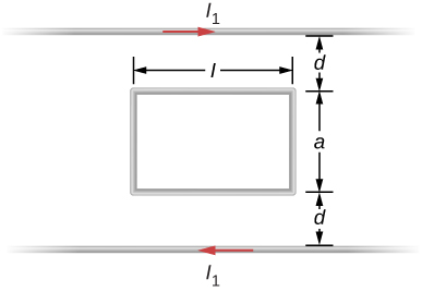
A small, rectangular single loop of wire with dimensions l, and a is placed, as shown below, in the plane of a much larger, rectangular single loop of wire. The two short sides of the larger loop are so far from the smaller loop that their magnetic fields over the smaller fields over the smaller loop can be ignored. What is the mutual inductance of the two loops?
Suppose that a cylindrical solenoid is wrapped around a core of iron whose magnetic susceptibility is x. Using Equation 14.9, show that the self-inductance of the solenoid is given by
where l is its length, A its cross-sectional area, and N its total number of turns.
A solenoid with turns/m has an iron core placed in it whose magnetic susceptibility is . (a) If a current of 2.0 A flows through the solenoid, what is the magnetic field in the iron core? (b) What is the effective surface current formed by the aligned atomic current loops in the iron core? (c) What is the self-inductance of the filled solenoid?
a. 100 T; b. 2 A; c. 0.50 H
A rectangular toroid with inner radius outer radius , height , and turns is filled with an iron core of magnetic susceptibility . (a) What is the self-inductance of the toroid? (b) If the current through the toroid is 2.0 A, what is the magnetic field at the center of the core? (c) For this same 2.0-A current, what is the effective surface current formed by the aligned atomic current loops in the iron core?
The switch S of the circuit shown below is closed at . Determine (a) the initial current through the battery and (b) the steady-state current through the battery.
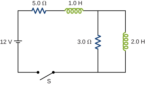
a. 0 A; b. 2.4 A
In an oscillating RLC circuit, . Initially, the capacitor has a charge of and the current is zero. Calculate the charge on the capacitor (a) five cycles later and (b) 50 cycles later.
A 25.0-H inductor has 100 A of current turned off in 1.00 ms. (a) What voltage is induced to oppose this? (b) What is unreasonable about this result? (c) Which assumption or premise is responsible?
a. ; (b) The voltage is so extremely high that arcing would occur and the current would not be reduced so rapidly. (c) It is not reasonable to shut off such a large current in such a large inductor in such an extremely short time.
Challenge Problems
A coaxial cable has an inner conductor of radius a, and outer thin cylindrical shell of radius b. A current I flows in the inner conductor and returns in the outer conductor. The self-inductance of the structure will depend on how the current in the inner cylinder tends to be distributed. Investigate the following two extreme cases. (a) Let current in the inner conductor be distributed only on the surface and find the self-inductance. (b) Let current in the inner cylinder be distributed uniformly over its cross-section and find the self-inductance. Compare with your results in (a).
In a damped oscillating circuit the energy is dissipated in the resistor. The Q-factor is a measure of the persistence of the oscillator against the dissipative loss. (a) Prove that for a lightly damped circuit the energy, U, in the circuit decreases according to the following equation.
where
(b) Using the definition of the Q-factor as energy divided by the loss over the next cycle, prove that Q-factor of a lightly damped oscillator as defined in this problem is
(Hint: For (b), to obtain Q, divide E at the beginning of one cycle by the change over the next cycle.)
proof
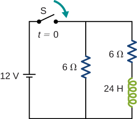
The switch in the circuit shown below is closed at . Find currents through (a) , (b) , and (c) the battery as function of time.
A square loop of side 2 cm is placed 1 cm from a long wire carrying a current that varies with time at a constant rate of 3 A/s as shown below. (a) Use Ampère’s law and find the magnetic field. (b) Determine the magnetic flux through the loop. (c) If the loop has a resistance of , how much induced current flows in the loop?
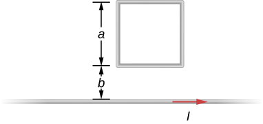
a. b. ; c. 4.4 nA
Glossary
- RLC circuit
- circuit with an ac source, resistor, inductor, and capacitor all in series.