In this section, we consider the problem of injecting light into a fiber optic cable. The problem is illustrated in Figure 8.3.
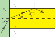
In this figure, we see light incident from a medium having index of refraction \(n_0\), with angle of incidence \(\theta^i\). The light is transmitted with angle of transmission \(\theta_2\) into the fiber, and is subsequently incident on the surface of the cladding with angle of incidence \(\theta_3\). For light to propagate without loss within the cable, it is required that
since this criterion must be met in order for total internal reflection to occur.
Now consider the constraint that Equation 8.5 imposes on \(\theta^i\). First, we note that \(\theta_3\) is related to \(\theta_2\) as follows:
therefore
so
Squaring both sides, we find:
Now invoking a trigonometric identity:
so:
Now we relate the \(\theta_2\) to \(\theta^i\) using Snell’s law:
so Equation 8.12 may be written:
Now solving for \(\sin\theta^i\), we obtain:
This result indicates the range of angles of incidence which result in total internal reflection within the fiber. The maximum value of \(\theta^i\) which satisfies this condition is known as the acceptance angle \(\theta_a\), so:
This leads to the following insight:
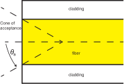
In order to effectively launch light in the fiber, it is necessary for the light to arrive from within a cone having half-angle \(\theta_a\) with respect to the axis of the fiber.
The associated cone of acceptance is illustrated in Figure 8.4.
It is also common to define the quantity numerical aperture NA as follows:
Note that \(n_0\) is typically very close to \(1\) (corresponding to incidence from air), so it is common to see NA defined as simply \(\sqrt{ n_f^2 - n_c^2 }\). This parameter is commonly used in lieu of the acceptance angle in datasheets for fiber optic cable.
Example 8.2
Acceptance angle.
Typical values of \(n_f\) and \(n_c\) for an optical fiber are 1.52 and 1.49, respectively. What are the numerical aperture and the acceptance angle?
Solution. Using Equation 8.17 and presuming \(n_0=1\), we find NA \(\cong \underline{0.30}\). Since \(\sin\theta_a =\) NA, we find \(\theta_a=\underline{17.5^{\circ}}\). Light must arrive from within \(17.5^{\circ}\) from the axis of the fiber in order to ensure total internal reflection within the fiber.
Additional Reading:
“Optical fiber” on Wikipedia.
“Numerical aperture” on Wikipedia.