1.3 Coordinate Systems

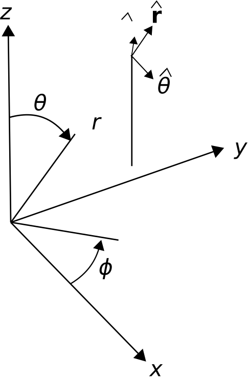
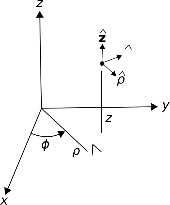
The coordinate systems most commonly used in engineering analysis are the Cartesian, cylindrical, and spherical systems. These systems are illustrated in Figures 1.1, 1.2, and 1.3, respectively. Note that the use of variables is not universal; in particular, it is common to encounter the use of \(r\) in lieu of \(\rho\) for the radial coordinate in the cylindrical system, and the use of \(R\) in lieu of \(r\) for the radial coordinate in the spherical system.
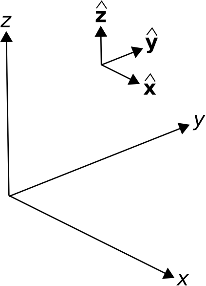
Shows the Cartesian coordinate system. Overlayed on this are basis vectors x-hat, y-hat, and z-hat corresponding to the axes of the coordinate system.
Figure 1.1. Cartesian coordinate system. © K. Kikkeri CC BY SA 4.0
Cartesian coordinate system with a point arbitrarily plotted in the positive x, y, and z axes. A dashed line in the xy-plane labeled rho indicates the point’s distance from the z-axis and is shown at an angle phi from the x-axis. Another dashed line labeled z is perpendicular to rho, extends vertically from the xy-plane, and connects to the plotted point. The point has vector z-hat pointed in the z-direction. rho-hat points away from the origin, parallel to rho. phi-hat is perpendicular to z-hat and rho-hat.
Figure 1.2. Cylindrical coordinate system. © K. Kikkeri CC BY SA 4.0
Cartesian coordinate system with a point arbitrarily plotted in the positive x, y, and z axes. A dashed line forms an acute triangle with one point at the origin of the Cartesian coordinate system and the top point connected to the arbitrary point with hypotenuse labeled r. The angle from the x-axis to the bottom side of the triangle is labeled phi. The angle from the z-axis to the hypotenuse is labeled theta. From the arbitrary point, vectors labeled phi-hat, r-hat, and theta-hat extend. The phi-hat vector extends parallel to the z-axis. Theta-hat extends parallel to the x-axis. R-hat is perpendicular to phi-hat and theta-hat.
Figure 1.3. Spherical coordinate system. © K. Kikkeri CC BY SA 4.0

Additional Reading: