Solutions to the electromagnetic wave equations (Section 9.2) exist in a variety of forms, representing different types of waves. It is useful to identify three particular geometries for unguided waves. Each of these geometries is defined by the shape formed by surfaces of constant phase, which we refer to as phasefronts. (Keep in mind the analogy between electromagnetic waves and sound waves (described in Section 1.3), and note that sound waves also exhibit these geometries.)
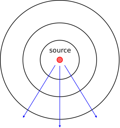
A spherical wave has phasefronts that form concentric spheres, as shown in Figure 9.1. Waves are well-modeled as spherical when the dimensions of the source of the wave are small relative to the scale at which the wave is observed. For example, the wave radiated by an antenna having dimensions of 10 cm, when observed in free space over a scale of 10 km, appears to have phasefronts that are very nearly spherical. Note that the magnitude of the field on a phasefront of a spherical wave may vary significantly, but it is the shape of phasefronts that make it a spherical wave.
A cylindrical wave exhibits phasefronts that form concentric cylinders, as shown in Figure 9.2. Said differently, the phasefronts of a cylindrical wave are circular in one dimension, and planar in the perpendicular direction. A cylindrical wave is often a good description of the wave that emerges from a line-shaped source.

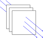
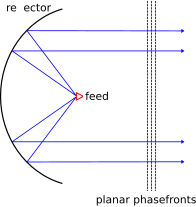
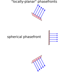
A plane wave exhibits phasefronts that are planar, with planes that are parallel to each other as shown in Figure 9.3. There are two conditions in which waves are well-modeled as plane waves. First, some structures give rise to waves that appear to have planar phasefronts over a limited area; a good example is the wave radiated by a parabolic reflector, as shown in Figure 9.4. Second, all waves are well-modeled as plane waves when observed over a small region located sufficiently far from the source. In particular, spherical waves are “locally planar” in the sense that they are well-modeled as planar when observed over a small portion of the spherical phasefront, as shown in Figure 9.5. An analogy is that the Earth seems “locally flat” to an observer on the ground, even though it is clearly spherical to an observer in orbit. The “locally planar” approximation is often employed because it is broadly applicable and simplifies analysis.
Most waves are well-modeled as spherical, cylindrical, or plane waves.
Plane waves (having planar phasefronts) are of particular importance due to wide applicability of the “locally planar” approximation.