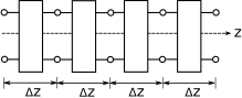
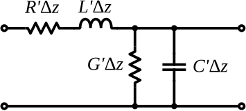
It is possible to ascertain the relevant behaviors of a transmission line using elementary circuit theory applied to a differential-length lumped-element model of the transmission line. The concept is illustrated in Figure 3.9, which shows a generic transmission line aligned with its length along the \(z\) axis. The transmission line is divided into segments having small but finite length \(\Delta z\). Each segment is modeled as an identical two-port having the equivalent circuit representation shown in Figure 3.10. The equivalent circuit consists of 4 components as follows:
The resistance \(R'\Delta z\) represents the series-combined ohmic resistance of the two conductors. This should account for both conductors since the current in the actual transmission line must flow through both conductors. The prime notation reminds us that \(R'\) is resistance per unit length; i.e., \(\Omega\)/m, and it is only after multiplying by length that we get a resistance in \(\Omega\).
The conductance \(G'\Delta z\) represents the leakage of current directly from one conductor to the other. When \(G'\Delta z>0\), the resistance between the conductors is less than infinite, and therefore, current may flow between the conductors. This amounts to a loss of power separate from the loss associated with \(R'\) above. \(G'\) has units of S/m. Further note that \(G'\) is not equal to \(1/R'\) as defined above. \(G'\) and \(R'\) are describing entirely different physical mechanisms (and in principle either could be defined as either a resistance or a conductance).
The capacitance \(C'\Delta z\) represents the capacitance of the transmission line structure. Capacitance is the tendency to store energy in electric fields and depends on the cross-sectional geometry and the media separating the conductors. \(C'\) has units of F/m.
The inductance \(L'\Delta z\) represents the inductance of the transmission line structure. Inductance is the tendency to store energy in magnetic fields, and (like capacitance) depends on the cross-sectional geometry and the media separating the conductors. \(L'\) has units of H/m.
In order to use the model, one must have values for \(R'\), \(G'\), \(C'\), and \(L'\). Methods for computing these parameters are addressed elsewhere in this book.