Two common types of transmission line are coaxial line (Figure 3.2) and microstrip line (Figure 3.3). Both are examples of transverse electromagnetic (TEM) transmission lines. A TEM line employs a single electromagnetic wave “mode” having electric and magnetic field vectors in directions perpendicular to the axis of the line, as shown in Figures 3.4 and 3.5. TEM transmission lines appear primarily in radio frequency applications.
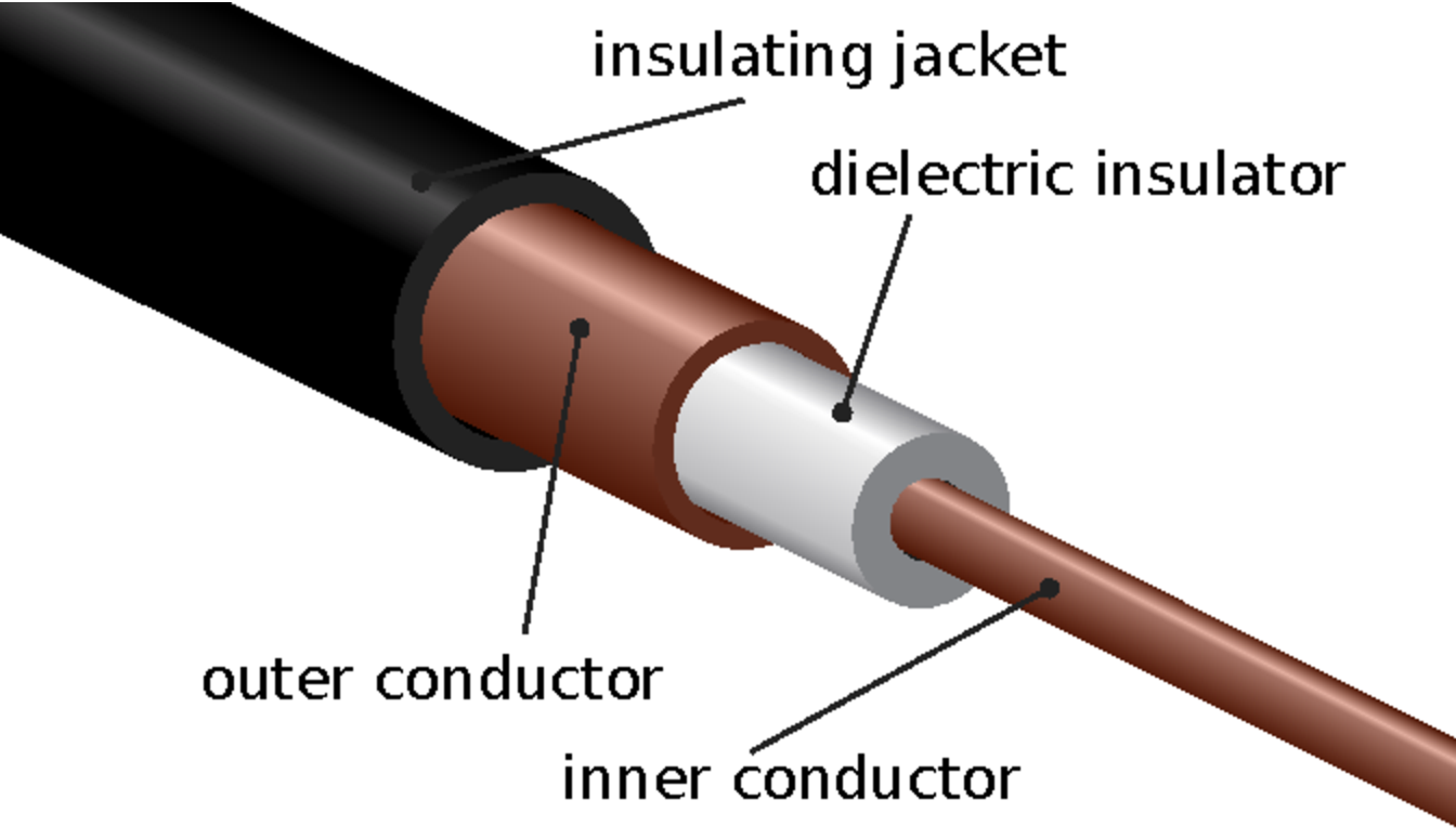
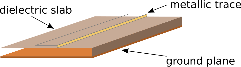
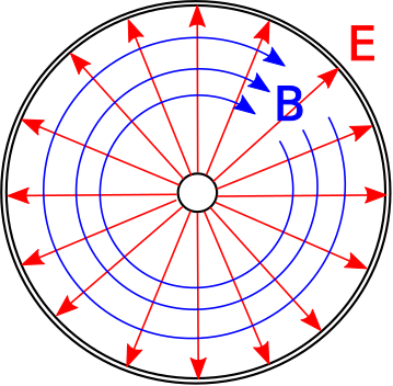
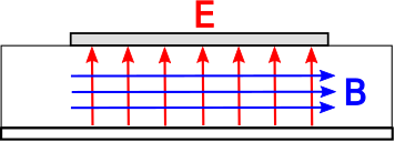
TEM transmission lines such as coaxial lines and microstrip lines are designed to support a single electromagnetic wave that propagates along the length of the transmission line with electric and magnetic field vectors perpendicular to the direction of propagation.
Not all transmission lines exhibit TEM field structure. In non-TEM transmission lines, the electric and magnetic field vectors that are not necessarily perpendicular to the axis of the line, and the structure of the fields is complex relative to the field structure of TEM lines. An example of a transmission line that exhibits non-TEM field structure is the waveguide (see example in Figure 3.6). Waveguides are most prevalent at radio frequencies, and tend to appear in applications where it is important to achieve very low loss or where power levels are very high. Another example is common “multimode” optical fiber (Figure 3.7). Optical fiber exhibits complex field structure because the wavelength of light is very small compared to the cross-section of the fiber, making the excitation and propagation of non-TEM waves difficult to avoid. (This issue is overcome in a different type of optical fiber, known as “single mode” fiber, which is much more difficult and expensive to manufacture.)

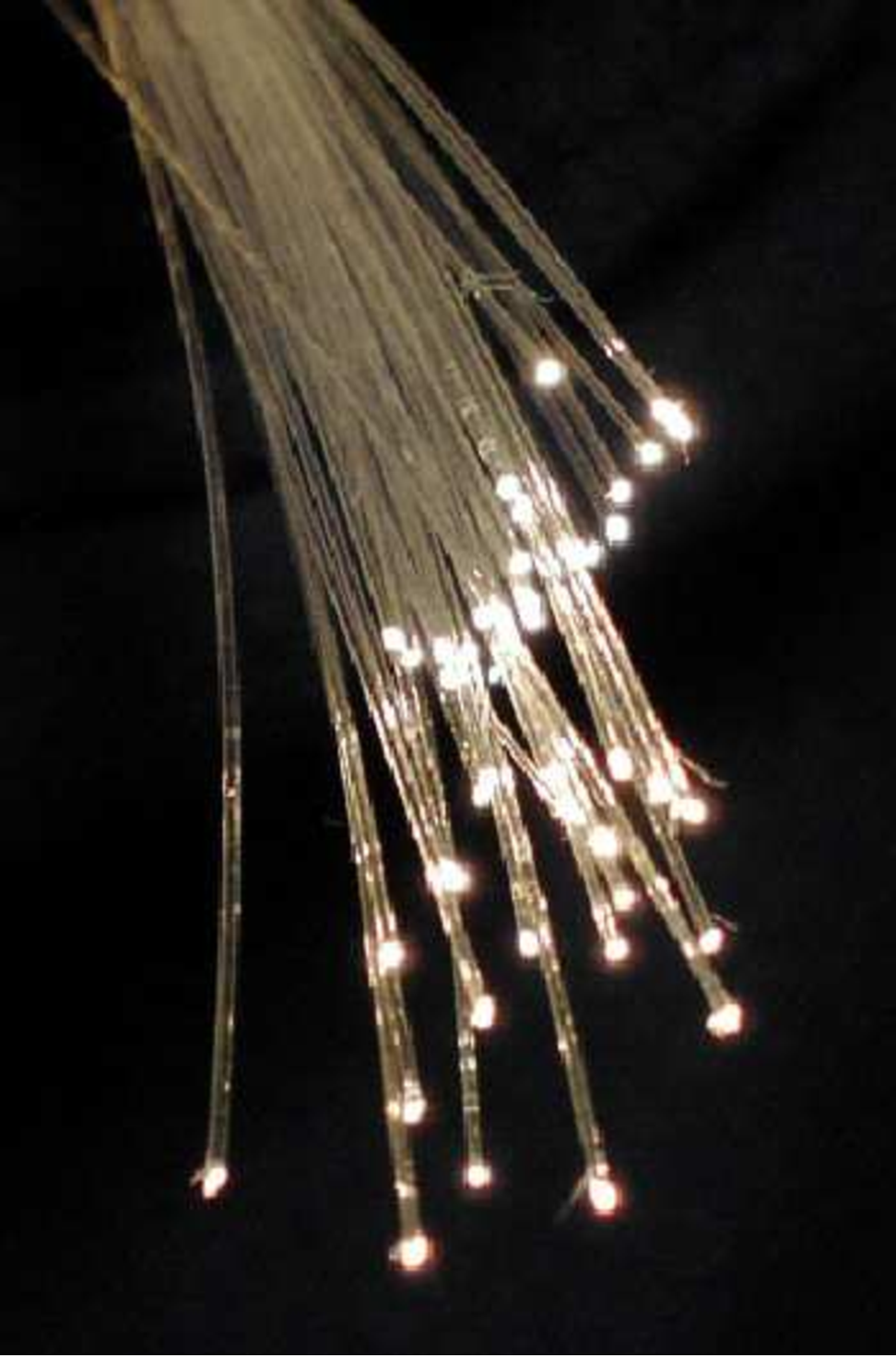
Higher-order transmission lines, including radio-frequency waveguides and multimode optical fiber, are designed to guide waves that have relatively complex structure.
Additional Reading:
“Coaxial cable” on Wikipedia.
“Microstrip” on Wikipedia.
“Waveguide (electromagnetism)” on Wikipedia.
“Optical fiber” on Wikipedia.